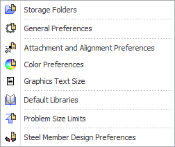
Once you have SPACE GASS installed and running, various settings and preferences can be changed via the Settings menu as shown below.
Note that all settings are saved in a number of files called SG.INI, SGSettings.GS and various XML files. They are all stored in the LocalAppData folder (eg. c:\Users\Peter\AppData\Local\SPACE GASS\14).
Resetting the configuration settings back to the factory defaults
Note that you can quickly reset SPACE GASS back to its default configuration settings by running the SPACE GASS Utility Tool (via the Start button => SPACE GASS 14 => SPACE GASS Utility 14) and clicking the "Reset Client Configuration" button. For more information, refer to The SPACE GASS utility tool.
You can use this form to set the locations of where the various types of SPACE GASS files reside. Any folders that do not exist are automatically created as you go.
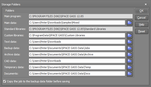
If the "Copy the Job to the Backup Data Folder Before Saving" option is ticked then whenever a job is saved, a copy of the previously saved version of the job is copied to the backup data folder and renamed with an extension of BAK. If you have lost an important job and wish to recover its BAK copy, you can either import it by choosing the "Import" option from the file menu or you can make a copy of the <Job>.BAK file, rename it to <Job>.SG and then open it as a normal job. Be careful, because each time you save the job, the BAK file will be overwritten by the previously saved version of the job and so you can only recover the most previous version.
For maximum program speed you should always set the "Temporary Data" folder to a local drive rather than a network drive.
The following settings are general purpose settings that control the behavior and appearance of various parts of SPACE GASS.
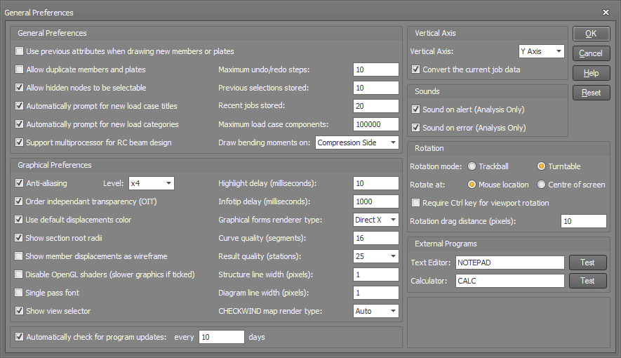
The "Use previous attributes when drawing new members or plates" option, if ticked, means that when you draw a new node, member or plate it will have the same properties (ie. section ID, material ID, etc) as the previous item you drew or selected.
The "Allow duplicate members and plates" option lets you draw members or plates on top of existing members or plates (ie. so that they share the same nodes).
The "Allow hidden nodes to be selectable" option allows you to select nodes that you can't see due to being behind other objects.
The "Automatically prompt for new load case titles" option enables load case titles to be prompted for automatically each time a new load case is created.
The "Automatically prompt for new load categories" option enables load categories to be prompted for automatically each time a load is created that doesn't have a load category.
The "Support multiprocessor for RC beam design" option allows multiple zones to be designed/checked simultaneously during a reinforced concrete beam design.
The "Maximum undo/redo steps" is the number of undo/redo steps that are remembered in the renderer. More memory is consumed if this setting is increased.
The "Previous selections stored" controls how many of your node/member/plate selections are remembered for later recall via Ctrl+R. You can use Ctrl+R to cycle through your previous selections.
The "Recent jobs stored" controls how many jobs can be accessed from the "Recent Jobs" list in the File menu.
The "Maximum load case components" is used to prevent memory overflow problems with large models that contain many load cases by limiting how many load cases can be displayed simultaneously. A "component" is considered to be a single diagram (eg. a load, a bending moment diagram, a shear force diagram, etc) on a single node, member or plate. If you experience memory problems when you try to display loads or analysis results graphically for many load cases simultaneously then you may need to lower this limit. Conversely, if your system has substantial memory and you are being restricted to an insufficient number of load cases when displaying loads or analysis results graphically then you could experiment with raising this limit.
The "Draw Bending Moments on" controls whether bending moments are drawn on the tension or compression side of a member.
The "Anti-aliasing" option gives graphical text a smooth appearance by changing the color of pixels around the edges of the text.
The "Order independent transparency (OIT)" option enables true (fully accurate) transparency for the display of transparent objects. If unticked (required by some older graphics cards) then the transparency is unsorted, resulting in some transparent objects appearing to be in front of objects that they should be behind.
The "Use default displacements color" option, if ticked, means that when only one load case is displayed, displacements are shown by member color rather than load case color. If unticked or if multiple load cases are displayed then displacements are colored by load case.
The "Show section root radii" controls whether the root radii of sections are shown when the model is displayed in rendered mode.
The "Show member displacements as wireframe" option lets you show displacements in wireframe even if the model is displayed in rendered or outline mode.
The "Disable OpenGL shaders" option should be unticked for maximum graphical performance in the renderer. If ticked (required for some older graphics cards) then the renderer uses a slow software emulation mode to display graphical objects rather than utilizing the parallel processing power of your graphics card. If SPACE GASS gives random error messages or is unstable or crashes then ticking this option should fix the problem, however due to the resulting substantial sacrifice in graphical performance you should upgrade the driver for your graphics card first to see if that fixes the problem. Disabling OpenGL shaders is a last resort option.
The "Single pass font" option is a fix for a bug in some graphics card drivers (including some NVIDIA Quadro cards). If you are getting small triangles instead of text on the graphics screen then try ticking this option.
The "Show view selector" option is used to show or hide the cube at the bottom-left corner of the graphics window.
The "Highlight delay" controls how long the mouse cursor must be near a node, member or plate before it becomes highlighted. Note that this setting has no effect over whether the node, member or plate is attached to when drawing new objects.
The "Infotip delay" controls how long the mouse cursor must be near a node, member or plate before its infotip appears.
The "Graphical forms renderer type" option controls which rendering engine is used in the graphical parts of the shape builder, portal frame builder, moving loads generator, steel connection design, RC beam design and RC column design modules. It should generally be set to DirectX for best results in those forms, however if SPACE GASS crashes or displays error messages when opening one of those forms then you may wish to change it to OpenGL or CPU to see if that fixes the problem. CPU is the slowest of the three settings and should only be used as a last resort if you are having problems with DirectX or OpenGL. Before changing to CPU you should upgrade the driver for your graphics card because an out of date driver is very often the cause of problems with DirectX and OpenGL.
The "Curve quality" controls how many segments are used to display curved objects such as cylinders and the like.
The "Result quality" controls how many short straight lines are used to approximate a curve when drawing deflected shapes, bending moment diagrams, etc.
The "Structure line width" is the thickness of lines used to draw the structure when in wireframe or outline modes.
The "Diagram line width" is the thickness of lines used to draw diagrams such as bending moment diagrams, etc.
The "CHECKWIND map render type" defaults to "Auto", however if the circular overlay showing the wind direction segments in CHECKWIND is not smooth or if it wobbles while being displayed then changing to a different render type could fix this. The best setting depends on your graphics card and so it is usually a matter of trial and error to determine which render type works best for you.
The "Automatically check for program updates" option allows SPACE GASS to automatically check for updates when it starts. This is done regularly in accordance with the number of days specified. If an update is available then you will be alerted via a message.
The "Vertical axis" setting only affects how the model is shown visually and doesn’t affect the local axis definitions or the analysis and design modules in any way. If you switch from Y vertical to Z vertical or vice-versa without changing any of the job data, the model will appear to be rotated 90 degrees about the X axis. If you want to be able to switch vertical axes while visually keeping the model unchanged then you should ensure that the "Convert the current job data" option is ticked. This will convert the job data so that any data items that are related to the global Y or Z axes will be interchanged, sometimes with sign changes. This will affect node coordinates, node restraints, master-slave constraints, global member offsets, member direction angles/axes, plate direction axes and all global loads. Note that the logic behind having Y vertical by default comes from the fact that most 2D structural models are vertical and in the XY-plane, and so it seems logical to keep Y as vertical when the model is extended to 3D. If Y is vertical then any sloping members in SPACE GASS are by default aligned in a vertical plane. For more information refer to "Coordinate Systems".
The "Sound on alert" and "Sound on error" options allow you to turn on/off the beep that normally occurs after an analysis.
The "Rotation mode" controls how the model behaves when you rotate it with the mouse. Trackball mode lets the model rotate about all three axes, whereas Turntable mode prevents rotation about an axis normal to your computer screen. Trackball mode is a bit harder to control than Turntable.
The "Rotate at" setting controls the centre of rotation when you rotate the model by dragging with the left mouse button held down.
The "Require Ctrl key for viewport rotation" option stops the model from rotating when you drag the mouse with the left button held down unless you also have the Ctrl key held down. It is intended to avoid the problem of the model being rotated unintentionally when you are trying to select items or start a selection window.
The "Rotation drag distance" is the number of pixels that you can move the mouse while the left button is held down before it will start to rotate the model. It is used to avoid the problem of the model rotating unintentionally when you are trying to select items or start a selection window. If this problem occurs then try increasing the rotation drag distance slightly. This option is not applicable if the "Require Ctrl key for viewport rotation" option is ticked.
The "External programs" are the ones used if the "Text editor" or "Calculator" options from the File menu are selected.
Attachment and Alignment Preferences
The following settings control how SPACE GASS behaves when you draw new nodes, members or plates, or edit your model with the various graphical tools available.
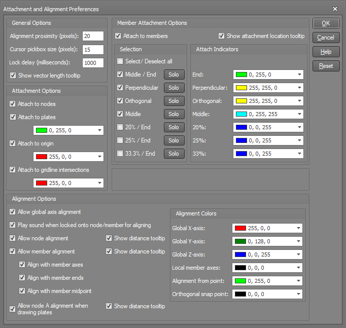
The "Alignment proximity" controls how close the mouse cursor must be to an axis aligned with a "locked on" node or member or a global axis in order to align with it.
The "Cursor pickbox size" is the size of the square that is attached to the mouse cursor when you are in a graphics tool. It controls how close the mouse cursor must be to a node, member or plate in order to select it, lock onto it or display its infotip.
The "Lock delay" controls how long the mouse cursor must be near a node, member or plate before you lock onto it.
The "Attachment options" control whether new items you draw will attach to existing nodes, members or plates if you click close to them (within the cursor pickbox size). If "Attach to plates" is ticked and you click anywhere on or near a plate then it will attach to the closest of the plate's nodes.
The "Member attachment options" allow you to select where on a member you can attach to. If you click on or near a member then it will attach to the closest of the ticked attachment points (ie. middle, end, perpendicular, orthogonal or a multiple of the % points).
The "Alignment options" control what happens after you lock onto a node, member or plate (by hovering over it for at least the lock delay period). Once you have locked onto an item, dashed lines that extend from the locked-on item allow you to accurately locate new points that line up with the locked-on item.
Note that when drawing members, plates or vectors, you don't have to wait for the lock delay before you can connect to an existing node or member. If the cursor pickbox touches or encloses an item then you can click immediately to connect to it.
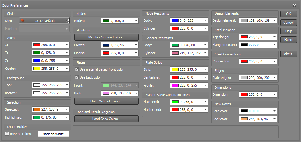
The following form lets you can change the theme of the renderer via the "Skin" setting. This affects the colors and styles of all the forms, buttons and input fields. You can also separately change the colors of most the items in your model to suit your requirements.
Load and analysis result diagrams are normally colored according to the load cases they belong to, and you can change the load case specific colors via the "Load Case Colors" button. Labels for those diagrams are also colored to match the diagram color by default, however you can set the labels to have their own independent color if desired via the "Labels" button. This can make it easier to read them.
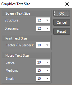
The size of the text displayed on the screen and in graphical prints can be controlled in the following form.
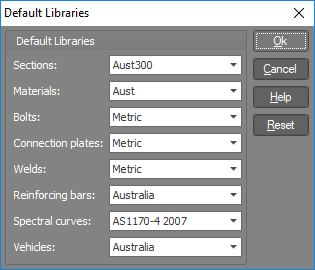
These are the libraries that SPACE GASS will try to access by default. You can of course use other libraries during normal operation without having to change the default libraries.
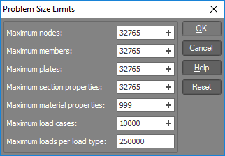
The problem size limits you set allow you to reserve space for a job, with space being allocated according to the size of each component of a job. You should set the limits high enough so that there is enough capacity for the largest of jobs that you are likely to encounter but small enough that you don't exceed the memory capacity of your computer.
Keep in mind that the limits can be changed at any time, even when you are halfway through inputting a job and find that you have run out of capacity. Just change the limits to suit your job size. After changing the limits you can simply return to where you left off, with all previously entered data retained.
Hard limits of 32765 currently apply to nodes, members and plates, however it is expected that these limits will be removed soon.
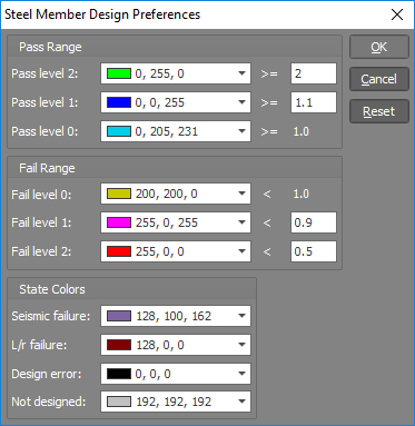
Steel Member Design Preferences
In the following form you can control the color and threshold of each pass or fail level when displaying steel member design results.