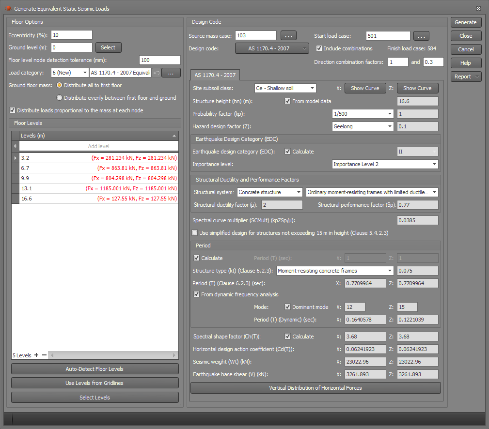
This tool allows you to generate seismic forces on a structure using the equivalent static method. The seismic forces are calculated at each specified floor level, and then distributed and applied as point loads at each node at the specified floor level.
You can run the tool by selecting "Generate Equivalent Static Seismic Loads" from the "Loads" menu or from the popup menu that appears if you right-click anywhere in the graphics area. The following form then appears that lets you specify the required parameters.
Assumptions
The equivalent static load generator makes the following assumptions:
Eccentricity
Earthquake loading codes generally require a load eccentricity to be included in the seismic load calculations when using the equivalent static method. The earthquake eccentricity is measured relative to the centre of mass of each floor level.
Ground level
Vital for determining floor heights; floors at/below ground level are excluded from the equivalent static analysis.
Floor level node detection tolerance
This tolerance is to allow for any variation in the vertical position of nodes in a floor. Nodes that are located within this tolerance from a specified floor level will be treated as part of the floor. You may need to increase it if you have step-downs or changes in elevation over part of a floor.
Load category
This field lets you specify which load category any generated seismic loads will go into. For more information refer to "Load categories".
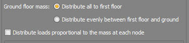
Ground floor mass
If the option "Distribute all to the first floor" is chosen, the mass of each element located between the ground and first floor will be allocated entirely to the first floor. Conversely, selecting "Distribute evenly between first floor and ground" results in distributing half the mass of each element in this range equally to both the ground and the first floor.
In scenarios where "Distribute loads proportional to the mass at each node" is not activated, the mass at each floor level will be evenly distributed among the nodes present at that particular floor. However, when this option is enabled, the total mass is distributed across the floor in a manner that is proportional to the mass present at each node.
Floor levels
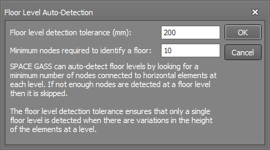
Earthquake loads are generated for each floor level specified in this table. If you have already defined some gridlines then the "Use Levels from Gridlines" button transfers the gridline levels into the "Levels" table. If you want to select the levels graphically then you can click the "Select Levels" button and then click a node at each level to have it put into the table. Finally, the "Auto-Detect Floor Levels" button looks for a minimum number of horizontal elements in a plane that would identify a floor. You can set a tolerance that allows for some variation in the height of the elements, plus you can control how many nodes within that tolerance are required to identify a floor level.
Source mass case
The source mass case is the load case/combination used to generate the equivalent static loads.
Note that only load cases that contain self-weight loads and/or lumped masses are considered when calculating equivalent static loads.
Design code
You can choose between AS 1170.4-2007 and NZS 1170.5:2004, with support for other earthquake codes to be added in the future.
Start load case
This section is to manage the load cases/combinations that are generated. In scenarios with no eccentricity, two earthquake load cases are created, corresponding to each direction of seismic activity. However, if an eccentricity is defined, four additional load cases are produced to account for both positive and negative eccentricities in each direction of seismic activity. The numbering of these load cases can be managed using the "Start load case" field.
When the "include combinations" checkbox is selected, appropriate combinations for earthquake loads are automatically generated. These combinations cover all four primary directions, incorporating both eccentricities and directional combination factors.
Note that the generated load combinations do not include vertical loads, only the generated lateral forces.
Direction combination factors
Earthquake loading codes typically mandate the simultaneous consideration of seismic forces along both horizontal axes. AS1170.4 specifies that the impacts from the two directions, when determined separately, should be combined by adding 100% of the horizontal earthquake forces from one direction and 30% from the perpendicular direction.
Code specific equivalent static seismic load parameters
You should refer to the relevant earthquake code for details of the code specific parameters shown below.
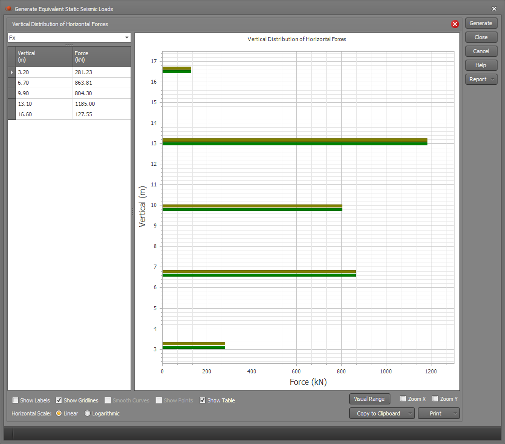
Vertical distribution of horizontal forces
If earthquake loads have been calculated, you can click the “Vertical Distribution of Horizontal Forces” button to view the calculated seismic forces at each level in a horizontal bar chart.
Report
At any stage you can click the "Report" button to get a report of the equivalent static seismic load calculations.
See also Lumped mass data.