Mesh plates (advanced)
This tool can be used to determine where selected plates intersect and create a refined mesh. It can therefore be used to connect intersecting plates, repair meshes with many invalid plates, refine the mesh for an entire model or a specific section of the model.
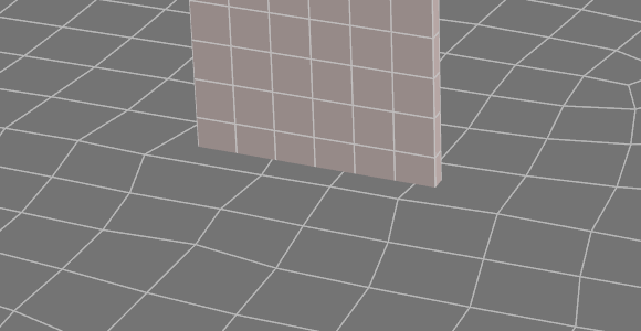
Slab and wall that are disconnected.
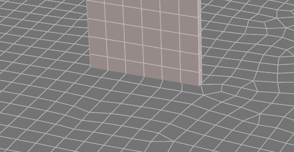
After selecting the wall and slab plate elements, then using the Mesh plates (advanced) tool, the slab and wall are connected and meshed.
In order to mesh plates, you should select the plates to be meshed, right-click and then select "Mesh Tools" => "Mesh Plates (Advanced)" from the popup menu that appears.
The form that appears next allows you to adjust the various settings that control the meshing.
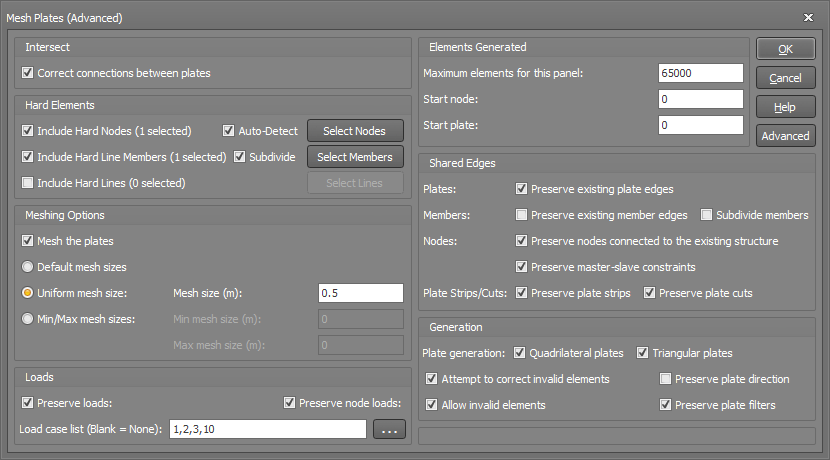
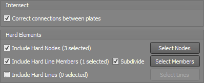
Intersect / Hard Elements
The "Intersect" and "Hard Elements" panels let you connect intersecting plates and define hard elements. To define hard elements, the "Correct connections between plates" checkbox needs to be selected.
The "Correct connections between plates" checkbox connects intersecting plates. It does this by first converting selected plates to triangular plates. It then calculates where the triangular plates intersect, subdivides them along the intersection lines and connects intersecting plates together.
The "Include Hard Nodes" input allows users to define nodes to be connected to the plate mesh.
The "Include Hard Line Members" input allows users to define members to be connected to the plate mesh.
The "Include Hard Lines" input allows users to define lines along the face of the plates. Nodes will be added along these lines and connected to the plate mesh.
Meshing Options
The "Meshing Options" panel lets you control the size of the plate elements to be generated when meshing the selected plates.
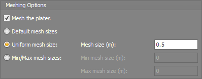
The "Mesh the plates" checkbox will mesh the selected plates to the specified element size/s.
The "Default mesh sizes" option, calculates the plate size based on the plates that are selected.
The "Uniform mesh size" option, generates plates with the specified uniform mesh size where possible.
The "Min/Max mesh sizes" option, generates plates within the specified Min/Max size range where possible.
Note that in order to achieve well conditioned elements while preserving compatibility with the surrounding elements, the requested element sizes may not always be achievable.
Loads
The "Loads" panel allows users to specify which loads are maintained when meshing. This is because any load on a plate or node places additional requirements on the mesh generation, when a model contains many load cases, sometimes it may not be possible to maintain all load cases and produce a high-quality mesh. For example, pressure loads can be applied to each plate element but not applied over part of a plate element. Therefore, the mesh will need to be generated so the edge of a pressure load area aligns with plate edges.
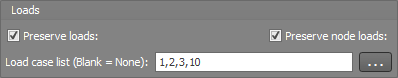
The "Preserve loads" option allows users to preserve plate loads when meshed for the specified load cases.
The "Preserve node loads" option allows users to preserve node loads when meshed for the specified load cases.
The "Load case list" input allows users to specify the load cases to preserve after the plates are meshed.
Elements Generated
The "Elements Generated" panel allows users to specify limits for the number of elements generated, the start node number and start plate number.
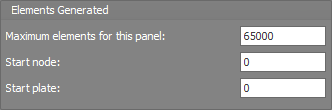
In order to prevent the mesh tool from generating an excessive number of elements, especially if you are unsure of the mesh size settings to use, the "Maximum elements for this panel" setting allows you to set an upper limit that will cause the mesh tool to stop if it is exceeded.
The numbering of nodes and plates being generated can be controlled to some extent via the "Start node" and "Start plate" settings. If set to zero, then the next available numbers will be used.
Shared Edges
The "Shared Edges" panel allows users to specify the settings for how plates, members, nodes, plate strips and plate cuts are treated during meshing.
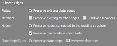
The "Preserve existing plate edges" setting identifies where an edge of a selected plate and unselected plate are both connected at either end, this option will then preserve these shared plate edges.
The "Preserve existing member edges" setting identifies where a member and an edge of a selected plate are both connected at either end, this option with then preserve these plate edges.
The "Subdivide members" setting will preserve nodes where members and selected plates are connected. When a member and an edge of a selected plate are connected at either end, then it will subdivide the member as required if additional nodes are created along the length of the member during meshing.
The "Preserve nodes connected to the existing structure" setting will preserve any nodes connected to the selected plates that are also connected to other members or unselected plates.
The "Preserve master-slave constraints" setting will preserve any nodes connected to the selected plates that have a master-slave constraint.
The "Preserve plate strips" setting will preserve nodes at the end of plate strips so the plate strip remains after meshing.
The "Preserve plate cuts" setting will preserve nodes at the end of plate cuts so the plate cuts remain after meshing.
Generation
The "Generation" panel controls the settings regarding plate shape, invalid plates, plate direction and filters.
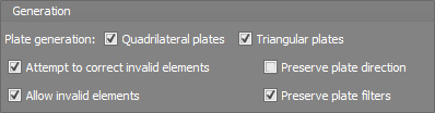
By default, the mesh tool will generate a mixture of quadrilateral and triangular elements, however you can limit it to just one type by unticking either "Quadrilateral plates" or "Triangular plates".
Invalid elements generally occur when an element has an aspect ratio greater than 4:1 or an internal angle greater than 135 degrees. If you tick the "Attempt to correct invalid elements" option then it will re-arrange the mesh and/or split problematic elements into two or three in an attempt to correct them.
Keep in mind that the "Attempt to correct invalid elements" option is not always successful and so occasionally you may get a warning about the mesh not being generated due to invalid elements. In such cases you could either change some of the mesh settings or tick the "Allow invalid elements" option and then once the mesh is generated use the "Find" tool to locate the invalid elements and attempt to correct them manually.
The "Preserve plate direction" setting will preserve the local axis direction of the selected plates.
The "Preserve plate filter" setting places additional requirements on how mesh is generated, such that the boundary of plates in every filter is maintained so that the filters can be preserved when new plates are generated.
Advanced
You can click the "Advanced" button to access the advanced settings. This allows users to specify additional parameters such as the "Intersect tolerance" to determine the tolerance applied when determining if plate elements intersect.
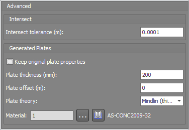
This form allows you to specify additional parameters such as the "Intersect tolerance" to determine the tolerance applied when determining if plate elements intersect.
Additionally, the original plate properties are maintained by default. However, specific plate thickness, plate offset, plate theory and material properties can be applied to the meshed plates.
For further information about other plate mesh tools refer to "Mesh tools".
See also Meshing overview.
See also Convert members to plates.
See also Generate plate mesh from members.
See also Advanced plate selection.