 button in
the side toolbar. For each column that provides support to a slab or which
is supported by a slab, the critical punching shear perimeter is calculated
and shown as a colored line on the slab.
button in
the side toolbar. For each column that provides support to a slab or which
is supported by a slab, the critical punching shear perimeter is calculated
and shown as a colored line on the slab.The punching shear check is independent of the strip method or finite
element method. It is a separate check that is performed by simply turning
on the punching shear perimeters via the button in
the side toolbar. For each column that provides support to a slab or which
is supported by a slab, the critical punching shear perimeter is calculated
and shown as a colored line on the slab.
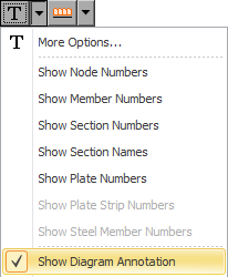
If you tick the "Diagram Annotation" option in the "Show Labelling and Annotation" menu then each punching shear perimeter will be labelled with its critical utilization ratio.
Any punching shear perimeters with a utilization ratio greater than 1.0 are shown in red so that they are immediately obvious. The punching shear results apply to the critical load case or combination from the load cases selected in the top toolbar.
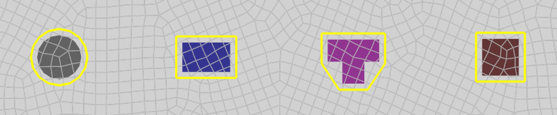
The critical punching shear perimeter generally follows the shape of the column's cross section at a distance of d/2 outside the column's perimeter, where d is the effective slab thickness at the face of the column. The value of d is calculated based on the average of the cover in each direction specified in the punching shear options form shown below. For columns that have concave corners such as you would get with a Tee shaped column, the critical punching shear perimeter is taken as the convex hull of the column cross section as shown below. Note that the "convex hull" of a cross section may be visualized as the shape assumed by a rubber band that has been stretched around the cross section.
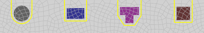
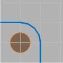
If the column is near an edge of the slab then the critical punching shear perimeter may terminate at the edge rather than continuing around the column. This is determined automatically and is reflected in the punching shear perimeter diagram as shown below.
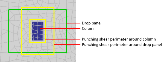
If drop panels are present then the punching shear may be higher outside the drop panel due to the thinner slab thickness there, even though the perimeter will be longer. In this case the punching shear module shows a second perimeter outside the drop panel. Note that if part of the punching shear perimeter passes through the drop panel then the thickness is conservatively taken to be equal to the slab thickness rather than the drop panel thickness. The following diagram shows a punching shear perimeter around the column and another one that extends to d/2 beyond the edge of the drop panel.
If you want to model column capitals and their effect on punching shear then you should subdivide your column at the lower end of the column cap and use the column cap cross section for the top section of the column. This will allow the punching shear checks to take into account the increased punching shear perimeter caused by the column cap.
In order to control the punching shear calculations you can set various parameters via the "Reinforcement Contour and Punching Shear Options" form as shown below. You can get to it via the arrow next to the punching shear button. Note that the "Yield strength of steel", "Min/Max reinforcement", "Wood-Armer moment adjustment" and "Reinforcement contour range" settings in the form do not apply to punching shear.
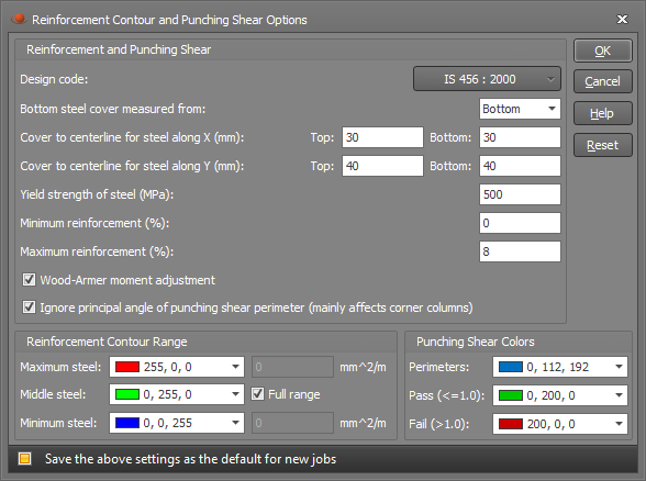
The "Design code" and "Cover" settings are shared with the reinforcement contours and so if you change them for the punching shear then the reinforcement contours will also be affected.
Design code
You can choose between various international design codes including AS3600 and IS456.
Because the punching shear check doesn't know the diameter of the actual bars or mesh used, the cover you specify must be measured to the center of the reinforcing bars or mesh. If you specify the cover to the edge of the reinforcement by mistake then your design will be unconservative! Note that cover in the strip method is the clear cover measured to the edge of the reinforcement because the actual bars and/or mesh are known.
The "Cover to centerline for steel along X" applies to the bars/wires running parallel to the local x-axis of the plate element and the "Cover to centerline for steel along Y" is for the bars/wires running in the other direction. Because the cover is measured to the centerline of the bars/wires, you must allow for the bar/wire diameter when setting it. The cover must also take into account in which direction each layer is running. In the above form it is assumed that the bars/wires running in the X direction are on top in the top face and on the bottom in the bottom face (ie. closest to the surface of the slab in both faces).
Note that the effective slab depth d used in the punching shear checks is based on the average of the cover in each direction. If the slab is supported by a column below then the effective depth is measured from the bottom of the slab/drop to the centerline of the top bars or if the slab supports a column above (eg. a raft footing) then the effective depth is measured from the top of the slab to the centerline of the bottom bars.
Ignore principal angle of punching shear perimeter (IS456 only)
If the punching shear perimeter forms a shape in plan that has a non-zero principal angle (ie. not a rectangle, circle, channel or U shape) then the punching shear calculations are affected for IS456. This generally only occurs with corner columns when the shear perimeter terminates at two different edges of the slab, however it can also happen with internal columns that have a cross section with a non-zero principal angle. Including the effect of a non-zero principal angle is more theoretically sound and more conservative than ignoring it, but many other programs ignore it and so this option is included for compatibility with those other programs.
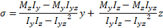
The following biaxial bending stress equation is used to calculate the shear stress along each boundary of the punching shear perimeter. If the "Ignore principal angle of punching shear perimeter" is ticked then the Iyz terms in the equation are ignored.
Punching shear colors
If no analysis results exist then the punching shear perimeters will be shown in the "Perimeters" color. If analysis results exist then they will be shown in the "Pass" or "Fail" color, depending on whether they have passed or failed.
Querying punching shear results
You can graphically query the punching shear results by right-clicking on a column and then selecting "Punching shear results" from the popup menu that appears. The query displays the perimeter length, punching shear stress, utilization ratio and other key values used in the calculation of the punching shear. You can then click on any other column to have the query form updated with the punching shear for that column.