This tool automatically creates multiple steel design members (also known as "design groups") from a selection of analysis members. Each generated steel design member can contain multiple analysis members connected end-to-end, provided they are of the same cross section, are generally collinear and don’t extend past a major axis support.
You can access the auto-create steel members tool by selecting "Steel Member Design Input-Auto create multiple steel members" from the Design menu or selecting "Auto-create multiple steel members" from the popup menu.
You can select analysis members from different locations throughout the model and with different section properties, and SPACE GASS will automatically sort through them and group them appropriately into steel design members.
You can even select the entire model and have all of the steel design members created automatically. However, you should check the generated members to ensure that their effective lengths, restraints and other data are correct.
The numbering convention adopted by this operation is such that the number of each generated steel design member is set to match the number of the first analysis member that it contains. This makes it easy to keep track of how the steel design members relate to the analysis members. However, please be aware that any existing steel design members that don’t follow this convention will be overwritten if their numbers clash with the new steel design members being generated. Of course, any steel design members that contain the selected analysis members will also be overwritten during the generation.
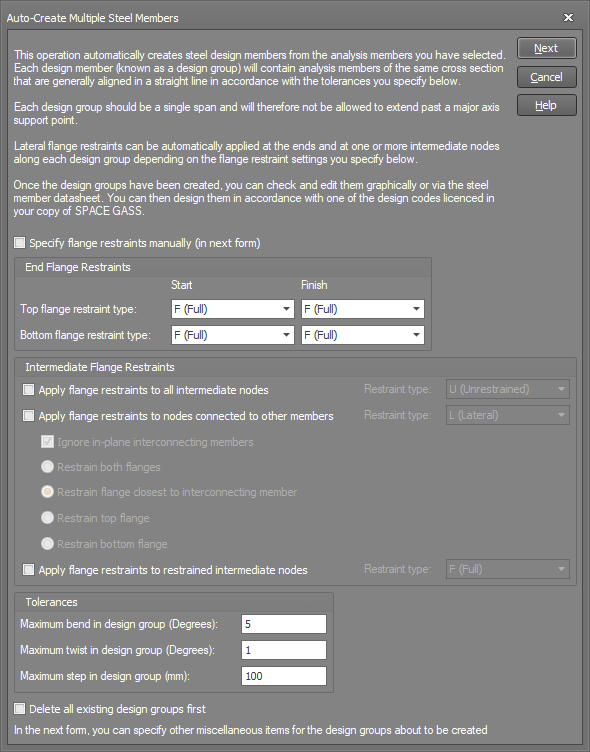
After you have selected the analysis members to be grouped into steel design members, click the right mouse button and select "Auto-create multiple steel members" from the popup menu (or select "Ok" if you initiated the operation from the menu). You can then specify restraint, effective length and other data for the generated steel members via the forms shown below.
Specify Flange Restraints Manually
Select this option if you want to directly specify all of the flange restraints along the generated steel members in the next form. Otherwise, the flange restraints will be placed in accordance with the data you specify in this form.
End Flange Restraints
These are the flange restraints that will be placed at the ends of the generated steel members.
Intermediate Flange Restraints
Flange restraints will be placed at the intermediate nodes along the generated steel members depending on which options you select in this area of the form. Your choices are any or all of the following:
Tolerances
The tolerances affect whether or not a selection of analysis members are suitable for grouping into a steel design member. A selection of analysis members of the same cross section connected end-to-end will be able to be grouped into a steel design member provided the bend angle, twist angle or step distance between adjacent analysis members do not exceed the tolerances you specify.
Delete all Existing Design Groups First
If you select this option, all steel design members will be deleted before the new steel members are generated. Otherwise, only those steel design members that contain the selected analysis members will be deleted before the generation.
After clicking the "Next" button, the following form appears. For detailed information about the data in the form, refer to "Steel member design data".
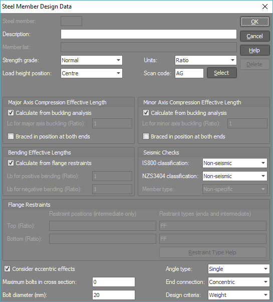
All steel design members generated will be created with the data that you specify in this form.
After the steel design members have been created, you should check each one, paying particular attention to the following:
You can show the steel design members graphically by clicking the ![]() button near the bottom of the side toolbar. They show up as thickened lines that are drawn slightly shorter than their actual length so that you can easily see where they start and finish.
button near the bottom of the side toolbar. They show up as thickened lines that are drawn slightly shorter than their actual length so that you can easily see where they start and finish.
Steel design members can be viewed or edited graphically on an individual basis as described in "Steel member input form", "Steel member input datasheet" or via the steel member design datasheet.
For an overview of the various methods available for inputting steel member design data, refer to "Steel member input methods".