You can run a steel member design or check by selecting one of the "Steel Member Design/Check" items from the Design menu.
Limit state codes such as AISC-LRFD, EUROCODE 3, AS4100, NZS3404, BS5950, IS800 and HK CP2011 require second order effects to be taken into account by either performing a first order (linear) elastic analysis with moment magnification or a second order (non-linear) elastic analysis with no moment magnification. Because a non-linear analysis is generally more efficient and accurate than moment magnification, and because SPACE GASS has no facilities for moment magnification, it is recommended that a non-linear analysis be used at all times for these codes.
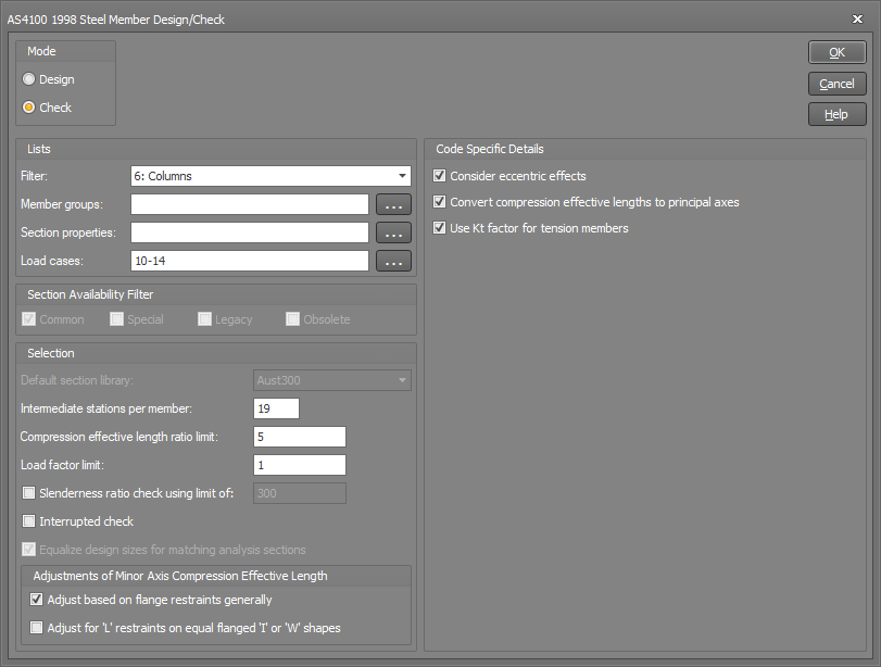
Design / Check mode
You can select between design mode or check mode as follows.
Design mode
Works its way up from the smallest library section that conforms with
the specified library scan
code until it finds a section that passes the code requirements
for the design group being designed.
Check mode
Just checks the section from the analysis data for the design group
being checked.
Note that SPACE GASS can now do a
steel member check using sections that haven't been imported from
a library, however you must have specified their steel design properties
via the Shape
builder.
Filter
You can select from any of the graphical filters to limit the design/check to the members defined in a filter. Alternatively, you can select "Filter in main toolbar" so that the members included in the design/check always match what is shown graphically. Further restrictions can also be applied by specifying member and section lists as explained below.
Member groups list
If you want to consider all design groups (for which steel member design data has been input) then this field can be left blank, otherwise you should type in a subset of design groups (separated by commas or dashes).
Section properties list
If you want to consider all design groups (or a subset as specified above), regardless of section type, leave this field blank. Otherwise, type in a list of section property numbers (separated by commas or dashes) to limit the number of design groups.
For example, if the columns in a frame all have section property number 3, you could instruct the program to design only the columns by entering "3" in the section properties list. Alternatively, you could type in all of the groups containing columns in the member groups list above, however this would be much more cumbersome.
Load cases list
If you want to consider all load cases then this field can be left blank, otherwise you should type in a list of incorporating the load cases (separated by commas or dashes) that you want considered.
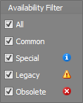
When in design mode, SPACE GASS will only select library sections that match what you have selected in the availability filter. For example, you could use this to prevent the design module from selecting sections that are obsolete or hard to obtain. The availability for each section is indicated in the library editor by an icon next to the section name. It is also listed in the properties of the section.
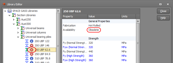
You can also limit which types of sections are shown in the library editor based on their availability by ticking the availability buttons at the bottom-right of the library editor.
Default section library
During the frame analysis section property input phase, sections that are read from a library have the library name stored with their section property data. Sections that have not been read from a library do not have a library name stored with their data.
For members with analysis section properties that were read from a library, the steel member design module uses that library to get information about the strength grade, properties, cross section shape, etc. of the member.
For members with analysis section properties that were not read from a library, the design module uses the default section library to get its information.
Intermediate stations per member
During the design process, each analysis member in a design group is subdivided into small increments using intermediate member stations. You must define the number of equally spaced intermediate stations that are to be positioned along each analysis member.
SPACE GASS automatically adds an extra station at each end of an analysis member, at each point of application of a concentrated member load, at each flange restraint position, and at the quarter points between flange restraints. If a design group consists of more than one analysis member then the member stations are simply added together to give a total number of stations for the design group as a whole.
The member stations are the points at which deflections, forces and moments are calculated. They are also the points at which code checks are carried out. It is therefore important that there are enough stations located along the design group to give a good representation of the deflected shape, bending moment diagram and shear force diagram so that the design results are accurate.
9 intermediate stations for each analysis member is normally quite accurate, however this can be increased to 75 if required. Note that the speed of the design process is approximately proportional to the number of stations per design group.
Compression effective length ratio limit
Because the compression effective lengths from a buckling analysis can sometimes be overestimated, you can specify an upper limit that will be imposed during the design phase.
Compression effective lengths from a buckling analysis are limited to Ratio x GLen, where Ratio is the compression effective length ratio limit that you specify and GLen is the overall design group length.
Note that this limit applies only to compression effective lengths from a buckling analysis and not to those specified directly.
See also Buckling effective lengths.
Load factor limit or Combined stress ratio limit
Firstly, the terms "load factor" and "combined stress ratio" are defined as follows.
The load factor applies to all limit state codes such as AISC-LRFD, EUROCODE 3, AS4100, AS4600, BS5950, NZS3404, IS800 and HK CP2011. It is the amount by which the design actions can be increased before the point of failure is reached.
For example, if the steel design returns a load factor of 1.12, you could theoretically increase your loads by 12%, repeat the analysis and design, and expect the load factor to reduce to 1.00. This is not always the case however, because the non-linearity of the analysis means that increasing your loads by 12% does not guarantee that the design actions will also increase by exactly 12%.
For members designed in accordance with these codes, the load factor must be greater than 1.0. This means that the design actions can be factored up by an amount greater than 1.0 before the member becomes inadequate.
![]() Because
the relationship between design actions and design capacity is not linear,
the load factor is not equal to the inverse of the (design actions)/(design
capacity) failure equation at the end of the detailed calculations for
each member in the steel design report.
Because
the relationship between design actions and design capacity is not linear,
the load factor is not equal to the inverse of the (design actions)/(design
capacity) failure equation at the end of the detailed calculations for
each member in the steel design report.
The combined stress ratio applies only to AISC-ASD, AS1250, SABS0162 and AS3990. It is the ratio of the actual stresses to the permissible stresses for the governing combined stress equation.
For members designed in accordance with AISC-ASD, AS1250, SABS0162 or AS3990, the combined stress ratio must be less than 1.0. This means that the combined stresses in the member are less than the combined permissible stresses.
During the design process, if the load factor is slightly less than 1.0 or if the combined stress ratio is slightly greater than 1.0, the member is deemed to have failed. In a real design situation however, you may decide to accept members which are very slightly overloaded. In order to cater for this reality, SPACE GASS allows you to decrease the load factor limit or increase the combined stress ratio limit so that the design program can accept a small amount of overload.
Alternatively, you can increase the load factor limit or decrease the combined stress ratio limit if you wish to design conservatively.
Slenderness ratio limit
This setting affects a simple slenderness ratio check that is only applicable to AISC-ASD, AISC-LRFD, AS1250, AS3990 and SA0162. The other codes have more sophisticated slenderness checks built into their standard equations.
For the applicable design codes, recommendations for maximum slenderness ratios range from 180 to 300 for struts, 300 to 350 for ties and 250 to 300 for beams. The maximum values depend on various factors including whether the predominant load is due to wind or not.
For tension members and members that have zero axial load, there is no slenderness check for compression effective lengths, however there is a slenderness check for bending effective lengths. Because of this, you may notice that in some cases the output report shows a value of l/r (compression) which exceeds the permissible l/r ratio without the member failing.
Interrupted check (check mode only)
If the checking procedure is uninterrupted, then after each member check, the results are saved and the program moves on to the next member regardless of the outcome of the check. Using this procedure, it is possible to check a large numbers of members without any operator intervention.
Alternatively, you can elect to have interrupted checking which causes the program to stop after each member check, notifying you of the results of the check and allowing you to manually select other member sizes for checking. If you decide not to try other member sizes, the program saves the results of the check and moves on to the next member.
Equalizing the design sizes for matching analysis sections
SPACE GASS allows you to specify that all members with the same analysis section property number should finish up with the same section size in the design results. Note that this only applies to running the steel member design module in "design" mode. For example, consider a portal frame with one analysis section for the two columns and another for the two rafters. When you perform a steel member design (as opposed to a check), you can specify that because the two columns share the same analysis section property number, their final design sizes should also match. Similarly, the two rafters can also be kept equal on each side because they share a single analysis section property number.
If this option is not selected, the design module will design each member independently rather than matching a single section size to all members that share the same analysis section property number. For the portal frame example mentioned above, this could results in four different member sizes rather than two.
Adjustment of minor axis compression effective lengths
Flange restraints capable of preventing lateral buckling of the flanges are sometimes also capable of preventing lateral buckling of the overall cross section. This depends on the type of the flange restraint and on the shape of the cross section and, if applicable, means that the minor compression effective length can be reduced to the length of the segment under consideration.
This happens regardless of whether the compression effective lengths are calculated from a buckling analysis or specified directly.
If you select the "Adjust based on flange restraints generally" check box, the minor compression effective length will be adjusted if:
both
ends of the segment have full or partial flange restraints; or
both
ends of the segment have full, partial or lateral flange restraints
and the member is a tube or box section.
If you also select the "Adjust for L restraints on equal flanged I or W shapes" check box then condition (b) above will also be extended to apply to equal flanged I or W shapes. Note, however, that there is some recent doubt as to whether lateral restraints on equal flanged I or W shapes can restrain the overall cross section laterally and therefore this check box defaults to off.
See also Buckling effective lengths.
Consider eccentric effects
Members such as angles, channels and Tees are sometimes connected at their ends by one flange or plate only. Depending on the shape of the section and the distance from the point of connection to the centroid of the section this can induce eccentric moments into the member.
This check box only affects the design groups that have eccentric effects enabled in their design input data. For design groups that have their individual eccentric effects disabled, this check box setting has no effect.
See also Eccentric effects for compression members.
See also Eccentric effects for tension members.
Convert single angle compression effective lengths
For single angle sections, the compression effective lengths must be input relative to the non-principal axes. These lengths are normally converted to principal axes during the design phase if required, however you can prevent this by unticking the "Convert single angle compression effective lengths" option. One reason for this might be that you have already input the compression effective lengths in principal axes and you don't want them to be converted.
Use Kt factor for tension members
When considering eccentric end connection effects, the extra eccentric moments are usually calculated and then added to the other bending moments in the member.
For tension members with AS4100/NZS3404, however the code allows you to use the above approach or simply ignore the extra eccentric moments and apply a correction factor (Kt) which is based on the cross section shape and the location of the point of connection (see AS4100/NZS3404 clause 7.3.2). By default the steel member design module defaults to using the Kt factor because it tends to give a more economical design in most cases, however you can elect to use the eccentric moments approach instead if you wish.
See also Eccentric effects for tension members.
Other factors
Various other factors can also be defined depending on the design code being used. They include AISC-ASD and AISC-LRFD U and Cb factors, Eurocode UK and Dutch factors, an AS4600 appendix F switch, IS800 Mcr, K and Cm factors, and HK CP2011 mLT factors.
![]() The
HK CP2011 module lets you choose between using clause 8.9.2 or clause
6.8.3. If you choose clause 8.9.2 then the analysis does not need to include
initial member imperfections or P-d
effects because they are accounted for in the design phase (although it
may be prudent for you to use both P-D and
P-d effects in
the analysis anyway). Alternatively, if you choose clause 6.8.3 then you
must include initial member imperfections and both P-D
and P-d effects
in the analysis.
The
HK CP2011 module lets you choose between using clause 8.9.2 or clause
6.8.3. If you choose clause 8.9.2 then the analysis does not need to include
initial member imperfections or P-d
effects because they are accounted for in the design phase (although it
may be prudent for you to use both P-D and
P-d effects in
the analysis anyway). Alternatively, if you choose clause 6.8.3 then you
must include initial member imperfections and both P-D
and P-d effects
in the analysis.
![]() The
HK CP2011 module also lets you choose how the Pcbar value is calculated
in equation 8.80. If you leave the "Calculate Pcbar in eq 8.80 based
on group length only" option unticked (the default) then Pcbar is
calculated from the minimum of Pcx and Pcy (based on the compression effective
lengths) but not allowed to go below a value of Pcbar based on the total
group length. Alternatively, if you tick this option then Pcbar is calculated
just based on the total group length. This latter approach is generally
conservative and is how SPACE GASS always calculated Pcbar before build
559 of SPACE GASS 12.5.
The
HK CP2011 module also lets you choose how the Pcbar value is calculated
in equation 8.80. If you leave the "Calculate Pcbar in eq 8.80 based
on group length only" option unticked (the default) then Pcbar is
calculated from the minimum of Pcx and Pcy (based on the compression effective
lengths) but not allowed to go below a value of Pcbar based on the total
group length. Alternatively, if you tick this option then Pcbar is calculated
just based on the total group length. This latter approach is generally
conservative and is how SPACE GASS always calculated Pcbar before build
559 of SPACE GASS 12.5.
Frame and Member Imperfections
Most design codes require you to include initial frame and member imperfections in the analysis. The analysis module does not do this automatically and so you must build the required imperfections into your model.
Frame imperfections can be modelled by applying notional horizontal forces or initial deflections to nodes. Member imperfections can be modelled by applying initial curvature to members. These must both be done in accordance with the relevant clauses of the design code you are using.
When all of the information has been entered, the SPACE GASS steel member design/check proceeds.
If you want to terminate the process before it is finished, just press ESC or the right mouse button. If you terminate the process in this way, the results for any groups that have already been designed or checked are saved.