This section describes the steel member design data that is required to be input before you can design and/or check steel members that are part of a frame analysis model.
For an overview of the various methods available for inputting steel member design data, refer to "Steel member input methods".
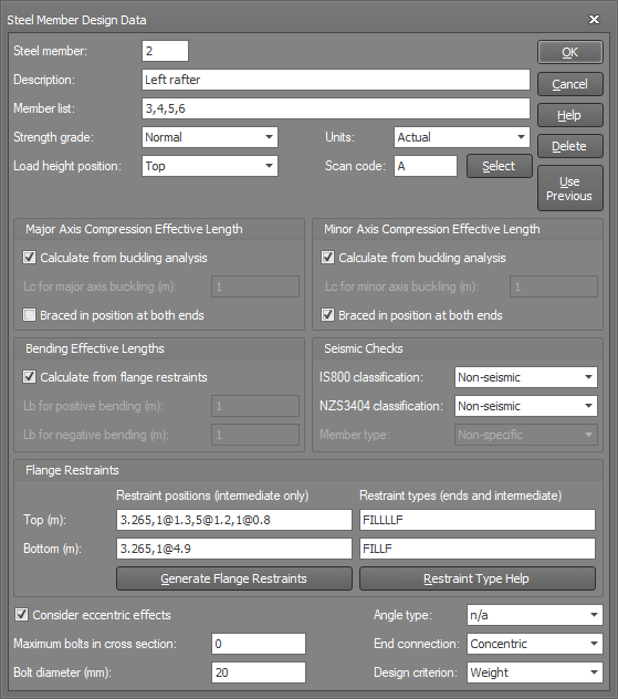
The form that appears when you input steel member design data graphically is shown above. The steel member datasheet contains the same information in a different format.
Group
Each steel design member is made up of one or more analysis members. Hence, the concept of steel design groups is introduced. A steel design group usually represents a single piece of steel in the real structure. It could be modelled as a single member or a number of members in the analysis model.
![]() In order to make
it easier to relate member numbers to group numbers, it is often a good
idea to give the design group the same number as the first member in the
group. Otherwise, there is sometimes a tendency to confuse member numbers
and group numbers when scanning the design output data. By default, SPACE
GASS will give a design group a number corresponding to the first of the
members selected (when performing a graphical steel frame data input).
You can, of course, change this if you wish.
In order to make
it easier to relate member numbers to group numbers, it is often a good
idea to give the design group the same number as the first member in the
group. Otherwise, there is sometimes a tendency to confuse member numbers
and group numbers when scanning the design output data. By default, SPACE
GASS will give a design group a number corresponding to the first of the
members selected (when performing a graphical steel frame data input).
You can, of course, change this if you wish.
Description
An optional brief description of the steel design group.
Member list
A list of analysis members to be combined into the steel design group. This is often only one member in each group.
![]() Because the top
flange for a steel design group is taken to be the same as the top flange
for the first member in the design group, it is important to control which
member comes first in the design group. Flange restraint positions are
also referenced from the end of the first member in the design group.
Because the top
flange for a steel design group is taken to be the same as the top flange
for the first member in the design group, it is important to control which
member comes first in the design group. Flange restraint positions are
also referenced from the end of the first member in the design group.
See also Member groups.
Strength grade
The strength grade for members can be set to normal or high. The actual yield strengths are taken from the standard section libraries supplied with SPACE GASS. All of these libraries can be viewed or edited (see also Section libraries).
Choices are: |
Normal, |
|
High. |
Units
The compression effective lengths and flange restraint positions can be specified as actual distances or as ratios of the design group length.
Choices are: |
Actual, |
|
Ratio. |
Load height position
The load height position is used to allow for the case when a member is subjected to a downwards load acting above its shear centre causing an increased tendency for the flange to buckle laterally (out-of-plane). The load height position can be set to "Top flange" if this occurs, or "Shear centre" if the predominant load is positioned at the shear centre or below such that it resists lateral buckling of the flange.
Choices are: |
Shear centre, |
|
Top flange. |
The load height position affects the value of the load height factor kl which is used to calculate the bending effective length of the member.

Destabilizing and stabilizing loads
See also Load height factor.
Scan code
In order to control the types of steel sections that the program selects during the course of a design, a library scan code is required. This allows you to select the types of sections that should only be considered for each member. For example, you could use it to tell the program that only I-sections were to be considered for the design of a portal frame column. Without the library scan code the program would simply choose the lightest adequate steel section from the library, regardless of its type or shape.
The library scan code is simply a list of up to four characters that contains the group codes of sections that are to be considered during the design of a member. You can input the scan code directly or click the "Select" button and then choose the section types you require and the scan code will be created for you.
Compression effective lengths (Lc major and minor)
These are the effective lengths for overall buckling about the major and minor axes due to axial compression. Depending on the "Units" selected, the Lc values may be expressed as an absolute length or as a ratio of the total group length.
Compression effective lengths can be calculated from a buckling analysis, however you can elect to input them directly if you prefer. To have them calculated, select the "Calculate from Buckling Analysis" check box. Of course to have Lc calculated, you must have the buckling analysis module (it is not a standard program feature) and you must run a buckling analysis before you can run the steel member design.
Having the Lc values calculated automatically is generally more efficient than specifying them directly because case specific Lc values can be calculated for each design load case. However, the buckling analysis sometimes over-estimates the Lc values for members that are not directly involved in the buckling of the model (refer to "Overestimation of compression effective lengths" in Buckling effective lengths for further information). If you specify Lc values directly then they are used for every load case.
If the Lc values are not being transferred automatically from a buckling analysis, but manually from the buckling effective length results, for design groups that consist of a number of analysis members connected end-to-end, you should use the MAXIMUM (not the sum!) of its individual analysis member effective lengths.
Spectral,
harmonic and transient response load cases cannot be included in a buckling
analysis. Furthermore, if you perform a buckling analysis on a combination
load case that contains a mixture of static with spectral, harmonic or
transient load cases, only the static load cases in that combination will
be analysed for buckling. This means that if you transfer member compression
effective lengths from a buckling analysis into a steel member design,
any spectral, harmonic or transient load cases considered in the design
will not contribute to the calculation of the compression effective lengths.
You should therefore consider specifying the compression effective lengths
manually in those cases.
The "Braced in Position at Both Ends of Group" check boxes indicate
whether or not the group is braced for each of the major and minor axis
directions. If you specify
that the group is braced then its compression effective length in the
direction you specify will not be allowed to exceed the overall group
length, regardless of whether it was calculated from a buckling analysis
or specified directly by you. Because this can substantially reduce
the effective lengths used in the design, please use this option with
care!
![]() It is sometimes useful
to model more than one structure in a single job, however this is not
recommended if you are performing a buckling analysis to obtain compression
effective lengths. The buckling analysis finds the lowest buckling load
factor for the entire model and then calculates the effective lengths
for all the members in the model based on that buckling load factor. For
example, if you have modelled structure A and structure B in one job,
and structure A has the lowest buckling load factor, the effective lengths
for structure B will be incorrectly based on the buckling load factor
from structure A. SPACE GASS can't detect if there are multiple structures
in a single model and therefore you need to put them into separate jobs
if you want to use effective lengths from a buckling analysis.
It is sometimes useful
to model more than one structure in a single job, however this is not
recommended if you are performing a buckling analysis to obtain compression
effective lengths. The buckling analysis finds the lowest buckling load
factor for the entire model and then calculates the effective lengths
for all the members in the model based on that buckling load factor. For
example, if you have modelled structure A and structure B in one job,
and structure A has the lowest buckling load factor, the effective lengths
for structure B will be incorrectly based on the buckling load factor
from structure A. SPACE GASS can't detect if there are multiple structures
in a single model and therefore you need to put them into separate jobs
if you want to use effective lengths from a buckling analysis.
![]() If
the compression effective lengths are calculated from a buckling analysis,
they are always taken from the first
buckling mode regardless of how many buckling modes were calculated.
If
the compression effective lengths are calculated from a buckling analysis,
they are always taken from the first
buckling mode regardless of how many buckling modes were calculated.
![]() During
the design phase, the compression effective lengths as calculated or defined
by you may be adjusted depending on parameters you specify at the start
of the design phase. For more information about this, refer to Running
a steel member design.
During
the design phase, the compression effective lengths as calculated or defined
by you may be adjusted depending on parameters you specify at the start
of the design phase. For more information about this, refer to Running
a steel member design.
![]() For
single angle sections, the compression effective lengths must be input
relative to the non-principal axes. For AS4100, BS5950, NZS3404, AS4600,
AISC-LRFD, AISC-ASD, HK CP2011, EUROCODE 3 and IS800, they are optionally
converted to the principal axes during the design/check phase. To prevent
this conversion, refer to Running
a steel member design.
For
single angle sections, the compression effective lengths must be input
relative to the non-principal axes. For AS4100, BS5950, NZS3404, AS4600,
AISC-LRFD, AISC-ASD, HK CP2011, EUROCODE 3 and IS800, they are optionally
converted to the principal axes during the design/check phase. To prevent
this conversion, refer to Running
a steel member design.
![]() In order to cater for all design code naming conventions, the compression
effective lengths are referred to as "Lc major" and "Lc
minor" in this document and in the data entry parts of the program.
However, in the design output reports, they are changed to match the notation
of the design code that was used.
In order to cater for all design code naming conventions, the compression
effective lengths are referred to as "Lc major" and "Lc
minor" in this document and in the data entry parts of the program.
However, in the design output reports, they are changed to match the notation
of the design code that was used.
See also Buckling effective lengths.
Bending effective lengths (Lb +ve and –ve)
Bending effective lengths for positive moments (Lb +ve) and for negative moments (Lb –ve) are normally calculated based on the flange restraints that you specify, however you can elect to input them directly if you prefer. To have them calculated, select the "Calculate from Flange Restraints" check box.
During the design, if you have elected to have the bending effective length calculated, it is taken as the length of the segment under consideration multiplied by three additional factors kt twist factor), kl (load height factor) and kr (lateral rotation factor) such that Lb = Lseg x kt x kl x kr.
Alternatively, if you have specified the bending effective length directly then the specified value is used without modification.
kt, kl and kr are fully explained in AS4100/NZS3404 clause 5.6.3. In AS1250, SABS0162, BS5950, AS3990, HK CP2011 and EUROCODE 3 there are no kt kl and kr factors and so SPACE GASS uses the rules of AS1250 clause 5.9, SABS0162 clause 7.2.3, BS5950 clause 4.3.5, AS3990 clause 5.9, HK CP2011 clause 8.3.4, IS800 clause 8.3.1 or EUROCODE 3 clause F.1.2 to calculate equivalent kt, kl and kr factors which, when multiplied together, produce an overall effective length factor kb.
![]() Because the steel member design module can't detect if the member being
designed is a cantilever or not, it is recommended that for cantilevers
(for which the critical flange may be the tension flange) you check that
the calculated bending effective length is correct and, if not, specify
it manually.
Because the steel member design module can't detect if the member being
designed is a cantilever or not, it is recommended that for cantilevers
(for which the critical flange may be the tension flange) you check that
the calculated bending effective length is correct and, if not, specify
it manually.
![]() In order to cater for all design
code naming conventions, the bending effective length is referred to as
"Lb" in this document and in the data entry parts of the program.
However, in the design output reports, it is changed to match the notation
of the design code that was used.
In order to cater for all design
code naming conventions, the bending effective length is referred to as
"Lb" in this document and in the data entry parts of the program.
However, in the design output reports, it is changed to match the notation
of the design code that was used.
![]() For single angle sections,
the bending effective lengths are not converted (unlike the compression
effective lengths) and are simply used as specified or as calculated from
the flange restraints. This means that if the bending effective lengths
are required in principal axes (for design codes such as AS4100, BS5950,
NZS3404, AS4600, AISC-LRFD, AISC-ASD, HK CP2011, EUROCODE 3 and IS800)
and the flange restraints are in non-principal axes then you should just
specify the bending effective lengths manually in principal axes.
For single angle sections,
the bending effective lengths are not converted (unlike the compression
effective lengths) and are simply used as specified or as calculated from
the flange restraints. This means that if the bending effective lengths
are required in principal axes (for design codes such as AS4100, BS5950,
NZS3404, AS4600, AISC-LRFD, AISC-ASD, HK CP2011, EUROCODE 3 and IS800)
and the flange restraints are in non-principal axes then you should just
specify the bending effective lengths manually in principal axes.
Note however that for single angle sections, it is unclear whether or not lateral restraints applied to either leg are effective in providing any restraint to the section. Consequently, you should be very careful when applying lateral restraints to single angle sections and you should use them only if you are sure they are effective in restraining the section. SPACE GASS will apply them if you specify them and so the decision about whether or not they should be used is entirely up to you.
See also Twist factor.
See also Load height factor.
See also Lateral rotation factor.
New Zealand seismic checks (NZS3404 chapter 12)
Seismic checks for NZS3404 were added in SPACE GASS 12.20.205. In order to activate these checks for a particular steel member you must specify its seismic classification as category 1, 2, 3 or 4, and member type as beam, column, brace or non-specific. The following NZS3404 code clauses are checked:
Table 12.4 (items 1 and 3) - All member types.
Clause 12.4.1.2 - All member types.
Clause 12.5.2 - All member types.
Clause 12.5.3.1 - Braces.
Table 12.5 - All member types.
Clause 12.7.2.1 - Beams.
Clause 12.8.3.1(a) - Columns and braces.
Clause 12.8.3.1(b) - Columns.
Clause 12.8.3.1(c) - Columns and braces.
Clause 12.10.3.1 - Beams.
For a "Non-seismic" member classification, none of the above checks are performed. For a "Non-specific" member type (with category 1-4 classification), all of the above checks are performed.
Note that the item 1 check in NZS3404 Table 12.4 uses the actual yield stress rather than the 12 < t <= 20 mm grade reference yield stress.
Indian seismic checks (IS800 chapter 12)
Seismic checks for IS800 were added in SPACE GASS 12.27.368. In order to activate these checks for a particular steel member you must specify its seismic classification as an ordinary concentrically braced frame (OCBF), special concentrically braced frame (SCBF), ordinary moment frame (OMF) or special moment frame (SMF), and member type as beam, column, brace or non-specific. The following IS800 code clauses are checked:
Clause 12.3 and table 23 - All member types.
Clause 12.2.3 - Columns.
Clause 12.5.1 - Columns.
Clause 12.5.1.1 - Columns.
Clause 12.7.1.1 - All member types.
Clause 12.7.2.1 - Braces.
Clause 12.7.2.2 - Braces.
Clause 12.7.2.4 - Braces.
Clause 12.7.2.6 - Braces.
Clause 12.8.1.1 - All member types.
Clause 12.8.2.1 - Braces.
Clause 12.8.2.2 - Braces.
Clause 12.8.2.3 - Braces.
Clause 12.8.2.5 - Braces.
Clause 12.8.2.7 - Braces.
Clause 12.8.4.1 - Columns.
Clause 12.10.1.1 - All member types.
Clause 12.11.1 (steel grade check only) - All member types.
Clause 12.11.1.1 - All member types.
For a "Non-seismic" member classification, none of the above checks are performed. For a "Non-specific" member type (with OCBF, SCBF, OMF or SMF classification), only the "All member types" checks are performed.
The checks for "E250B steel of IS2062 only" in clauses 12.8.2.1 and 12.11.1 simply look for a yield stress of between 230MPa and 250MPa and an ultimate stress of 410MPa. Because these yield and ultimate stress properties apply equally to E250A, E205B and E250C steel, and because SPACE GASS can't detect the difference between them, it is up to the user to ensure that E250A and E250C steel is not used when clauses 12.8.2.1 or 12.11.1 apply.
It is up to the user to create the load combinations in clause 12.2.3 and include them in the list of load cases to be considered in the design/check. The IS800 module will identify the clause 12.2.3 load combinations SOLELY by the presence of a multiplying factor of 2.5 and will use those load combinations for columns ONLY if clause 12.5.1 is satisfied.
Any load combinations containing a multiplying factor of 2.5 will only be used if they are included in the list of load cases to be considered, seismic checks are activated, and clause 12.5.1 for columns is satisfied. Furthermore, only their axial forces will be considered.
Flange restraints
Flange restraint positions are referenced from the end of the first member in a design group. SPACE GASS assumes that there is a restraint at each end of a group and you should therefore specify the intermediate restraint positions only.
Restraint positions should be specified independently for the top and bottom flanges. Up to 100 intermediate positions can be specified for each flange. If there are no intermediate restraints for a particular flange then the restraint positions field should be left blank.
When specifying restraint positions, you can use @’s to specify relative positions or groups of equally spaced positions. For example, restraint positions of 1.2,2.4,3.6,4.8,6.0,6.6,7.2,7.8,8.4 could be specified as 5@1.2,4@0.6, or positions of 1.2,1.8,2.7,3.3 could be specified as 1.2,1@0.6,2.7,1@0.6.
Depending on the "Units" selected, the restraint positions may be expressed as an absolute distance or as a ratio of the total group length.
Flange restraint types must be specified for each intermediate restraint position and for the two ends of the design group. Refer to "Flange restraints" for restraint definitions.
Choices are: |
Full (F) |
|
Partial (P) |
|
Lateral (L) |
|
Full and rotational (R) |
|
Partial and rotational (S) |
|
Unrestrained at end (U) |
|
Continuous lateral restraint (C) |
|
Ignore segment (I) |
![]() The
top flange of a member is the flange on the positive local y-axis (or
z-axis if the section has been flipped) side of the member. The top flange
of a group as a whole is defined such that it is the same as the top flange
of the first member in the group.
The
top flange of a member is the flange on the positive local y-axis (or
z-axis if the section has been flipped) side of the member. The top flange
of a group as a whole is defined such that it is the same as the top flange
of the first member in the group.
You can verify graphically
which is the top flange by clicking the ![]() button near
the bottom of the side toolbar. It displays a small triangle that points
to the top flange of each member.
button near
the bottom of the side toolbar. It displays a small triangle that points
to the top flange of each member.
![]() For single angle sections, it is unclear
whether or not lateral restraints applied to either leg are effective
in providing any restraint to the section. Consequently, you should be
very careful when applying lateral restraints to single angle sections
and you should use them only if you are sure they are effective in restraining
the section. SPACE GASS will apply them if you specify them and so the
decision about whether or not they should be used is entirely up to you.
For single angle sections, it is unclear
whether or not lateral restraints applied to either leg are effective
in providing any restraint to the section. Consequently, you should be
very careful when applying lateral restraints to single angle sections
and you should use them only if you are sure they are effective in restraining
the section. SPACE GASS will apply them if you specify them and so the
decision about whether or not they should be used is entirely up to you.
See also Flange restraints.
See also Effective flange restraints.
Consider eccentric effects
For members that have eccentric end connections, you can elect to consider or ignore the resulting eccentric moments. Eccentric moments are only added if they increase the normal design moments.
Note that even if you select this check box, you can disable eccentric effects globally by deselecting the eccentric effects check box in the steel member design/check form.
Maximum bolts in cross section
In order to calculate the effective web and flange areas, and subsequent member capacities, the presence of bolt holes at the member ends must be taken into account. SPACE GASS requires you to estimate the number and diameter of bolts per cross section at the ends of each member to be designed or checked. A bolt count of zero indicates that the member end is welded.
During the design, SPACE GASS checks to see that the bolts per cross section specified can be fitted into the cross section. If not, the number is reduced to the maximum that can be accommodated. If the member is too small to take even a single bolt then the connection is assumed to be welded.
Bolt diameter
End connection bolt diameter.
Angle type
In order to define the geometry of single or double angle sections, SPACE GASS requires the angle section type to be input.
Choices are: |
Single angle, |
|
Double angle with short legs connected, |
|
Double angle with long legs connected, |
|
Double angle starred (equal angles only). |
![]() Double
angle sections are assumed to have no space between the individual angle
sections.
Double
angle sections are assumed to have no space between the individual angle
sections.
! IMPORTANT NOTE !
The AS1250, SABS0162 and AS3990 modules assume that double angles are connected together at intermediate points sufficient to ensure that half of the design axial compressive force for the combined section does not exceed the compressive capacity of each angle section considered individually using an effective length (for buckling of the sections away from each other) equal to the distance between connection points.
The AISC-ASD & LRFD, EUROCODE 3, AS4100, NZS3404, BS5950, IS800 and HK CP2011 modules convert double angle sections into the equivalent Tee section and then treat them as a solid Tee shape. They do not support double starred angles.

Angle section orientation
All of the possible arrangements involving single and double angles are shown in the diagrams above. It is important to note that the major axis of a single or double angle section is assumed to be parallel to the short leg(s) of the section as shown in the diagrams.
![]() For
double equal angles, the long leg is assumed to be the vertical leg in
the diagrams above. Note that in SPACE GASS 10 and earlier, double equal
angle sections with long legs connected were adjusted internally and treated
as though their short legs were connected. This adjustment was removed
in SPACE GASS 11 and later versions.
For
double equal angles, the long leg is assumed to be the vertical leg in
the diagrams above. Note that in SPACE GASS 10 and earlier, double equal
angle sections with long legs connected were adjusted internally and treated
as though their short legs were connected. This adjustment was removed
in SPACE GASS 11 and later versions.
The design procedure for angle sections is considerably more complicated than for most other sections. This is due to the significant moments generated by eccentric end connections which cannot usually be avoided when working with angles. SPACE GASS is capable of taking these effects into account for both single and double angle sections.
![]() When
designing/checking single or double angle sections for AS1250, SABS0162
or AS3990, SPACE GASS considers only axial forces and shears. Normal bending
moments are not considered. The only moments considered are those due
to the eccentric end connections. This is not the case with the other
design modules. They consider all axial forces, shears and moments together
with any extra eccentric moments (if appropriate).
When
designing/checking single or double angle sections for AS1250, SABS0162
or AS3990, SPACE GASS considers only axial forces and shears. Normal bending
moments are not considered. The only moments considered are those due
to the eccentric end connections. This is not the case with the other
design modules. They consider all axial forces, shears and moments together
with any extra eccentric moments (if appropriate).
End connection
For non-symmetric members subjected to axial loads, such as angle sections, channels and Tees, the program needs to know which leg, flange or web is connected so that the extra moments due to possible eccentric end connections can be calculated (if appropriate).
Choices are: |
Concentric, |
|
Flange(s) (for I, H, T or channel sections), |
|
Web (for channel or T sections), |
|
Angle short leg, |
|
Angle long leg (vertical leg for equal angles before being flipped or a direction angle, direction node or direction axis applied). |
Design criteria
Most designs aim to minimize the structure weight, however if you are constrained to a certain member depth then you can elect to minimize the member depth instead.
Choices are: |
Weight, |
|
Depth. |
Use Previous button
Click the "Use Previous" button to set all the data in the form to the same as when the form was previously used.
See also Steel member input methods.
See also Steel member design text.
See also Running a steel member design.
See also Generate flange restraints.