The wavefront optimizer
The "Wavefront" solver uses a wavefront optimizer to temporarily re-organise the structure during the analysis phase to achieve close to the smallest possible stiffness matrix with the fastest possible analysis time. The "Paradise" solver uses a bandwidth optimizer to perform a similar task. The following discussion applies just to the wavefront optimizer.
The basic philosophy behind the wavefront optimizer is quite simple. It alters the order in which members and plates are loaded into the stiffness array by starting at one end of the structure and proceeding through it to the other end in one complete pass. Depending on the operating mode selected, the optimization can follow an irregular path, a straight line path or a circular path.
The optimizer usually reduces the frontwidth to within 95% of the optimum, however some structures such as large cubes which do not have a well defined "long dimension" can reduce its efficiency to almost 60%. Large cubic structures therefore may require careful member and/or plate numbering if they produce excessively large frontwidths.
If you have already numbered the members and plates to achieve the smallest possible frontwidth then the optimizer will of course not have much effect. If, however you have numbered the elements badly, the optimizer will probably have a dramatic effect. The most noticeable effect will be the smaller analysis time which is partly proportional to the frontwidth squared.
You can control the direction along which the optimization proceeds by selecting the optimization mode at the start of the analysis. The various optimization mode settings are described in the following sections.
Not activated
If the optimizer is not activated, the members and plates are loaded into the stiffness array in the order that they are numbered. If they have been badly numbered and the structure is large then excessive analysis times may result.
Auto mode
SPACE GASS trials the "General" and various "Linear" modes and then uses the one that gives the smallest frontwidth. It doesn't add significant time to the analysis and is the recommended setting.
General mode
SPACE GASS starts at the lowest numbered member or plate and then loads all of the elements that are connected directly to it. It then takes each of the connected elements in turn and loads all of the elements that are connected to them. This process continues until all elements in the structure have been loaded. This mode results in very efficient frontwidths for most structures.
Linear mode
This mode instructs the optimizer to proceed through the structure in a straight line direction parallel to one of the global X, Y or Z axes or along a vector that you specify. After you have specified linear mode, you must also nominate the axis or vector along which optimization will proceed. This should generally be in the direction of the long dimension of the structure.
Linear mode is ideally suited to long thin structures which have a well defined long dimension. The "long dimension" of a structure is not necessarily the dimension with the greatest length, rather it is defined such that if you make a cut through the structure at right angles to the long dimension at its widest point, you will cut through the least number of elements.
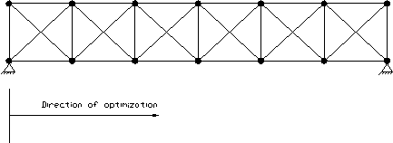
In the truss in the following diagram, the most efficient direction for the optimizer to proceed is horizontally. This is because a cut at right angles to the horizontal cuts through only four members.

Horizontal optimization

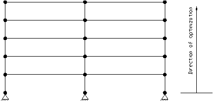
Vertical optimization
In the 2D multi-storey frame above, the most efficient direction for linear optimization is vertical even though the frame height is less than the frame width.
Circular mode
This mode instructs the optimizer to proceed through the structure around an arc with the axis of rotation parallel to one of the global X, Y or Z axes. After you have specified circular mode, you must also nominate the axis about which optimization will proceed, followed by the coordinates for the centre of rotation.
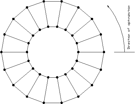
Circular mode is ideally suited to curved structures such as the circular frame shown following. Structures which are not perfectly circular but which have a general shape which is arranged around a central point can also be optimized very efficiently using circular mode. The centre of rotation should generally be near the centre of the structure, however this is not absolutely essential.

Circular optimization
Circular mode can also be used to great advantage with structures that require linear optimization in two directions.
A three dimensional multi-storey building model for example would probably require its primary optimization direction to be vertical. As the optimizer reached each floor, however a secondary horizontal direction would also need to be specified otherwise it would not know in which direction to go along the floor. Without a secondary direction, the optimizer would simply have to load the floor elements in the order of their numbering and this could result in an unnecessarily large frontwidth if the elements were badly numbered.
It is not possible to specify a primary and secondary direction with the optimizer in linear mode, however it is possible to do this in circular mode by having the centre of rotation a large distance away from the structure. Using circular mode in this way is very similar to linear mode except that as the optimizer progresses across (or up) the structure, the angle of attack also changes slightly as it moves around the arc.

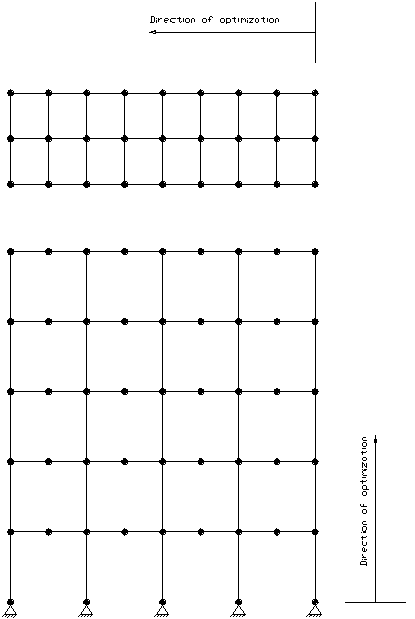
Bi-directional optimization
Consider for example the three dimensional multi-storey building model shown above. The primary optimization direction is vertical and the secondary direction for each floor is to the left. By using circular mode and positioning the centre of rotation at a large distance away from the model as shown in the following diagram, the desired result can be achieved.

Bi-directional optimization using circular mode
As the optimization line progresses up the structure, it reaches the right hand side of each floor before the left hand side. Thus, the structure as a whole is optimized from bottom to top and each floor is optimized from right to left.
Note that this method of optimization is usually the best way to deal with large cubic shaped structures.
![]() If you are not sure which optimizer mode to use for a particular structure, it is recommended
that you experiment with various modes to see how small a frontwidth can be achieved. You can do this by running the analysis and then terminating it by pressing ESC or the right mouse button after the frontwidth has been calculated and displayed
on the screen. Once you have found the most efficient mode, you can simply let the analysis continue to the end as normal.
If you are not sure which optimizer mode to use for a particular structure, it is recommended
that you experiment with various modes to see how small a frontwidth can be achieved. You can do this by running the analysis and then terminating it by pressing ESC or the right mouse button after the frontwidth has been calculated and displayed
on the screen. Once you have found the most efficient mode, you can simply let the analysis continue to the end as normal.