Deflection optimizer
The deflection optimizer uses the principles of virtual work to update selected members in your model in order to satisfy deflection limits, whilst keeping any mass increases to a minimum. For each member that could be changed, the optimizer evaluates how much changing the member size would influence the target deflection versus how much weight it would add to the structure. It then performs the changes based on reducing the deflections to their target limits for the smallest possible weight gain. A static analysis is performed at various stages during the optimization in order to monitor the deflections.
The optimizer was developed primarily for steel structures because the section libraries that come with SPACE GASS contain only steel sections, however if you create a custom section library containing sections for other materials then the optimizer can also be used with those materials.
After you have analysed the model you can run the optimizer by selecting "Deflection Optimizer" from the "Design" menu or from the popup menu that appears if you right-click anywhere in the graphics area. The following form then appears that lets you specify the optimization parameters.
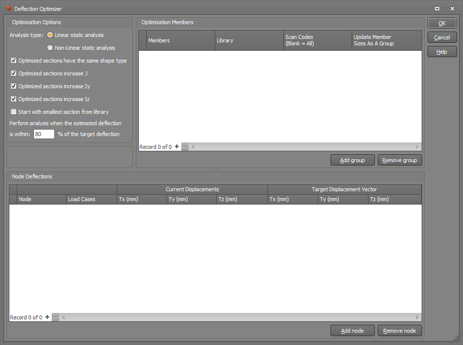
Optimization options
These options let you control the type of analysis to be performed and which section properties to consider when performing the optimization.
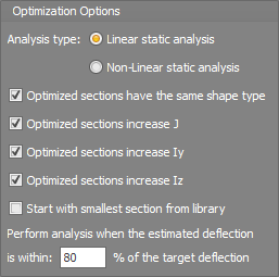
If "Optimized sections have the same shape type" is ticked then any members that are changed will keep their original cross section shape type. If unticked then an I-shape could change to a T-shape for example, although this is also controlled to some extent by the "Scan Codes" setting in the "Optimization Members" panel of the main form.
The optimization is usually based on a member's torsion constant and moments of inertia, however you can control this by unticking the J, Iy or Iz options if required. Axial and shear deformations are not included because they have very little effect on deflections compared to bending and torsion.
If the "Start with smallest section from library" is unticked then any member changes during the optimization always involve an increase in cross sectional area. If ticked then members could be changed to smaller sizes.
For speed, the optimizer simply factors up or down the deflections after making member changes. This is of course only approximate, especially if the analysis is non-linear, and so when a deflection gets within a user-defined percentage of its target value then a full analysis is performed. Whenever this happens you may notice it as a step or discontinuity in the Mass vs Required Deflection Reduction graph that is displayed at the end of the optimization.
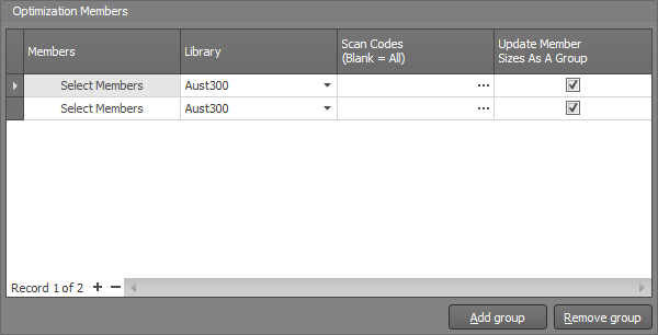
Optimization members
This panel lets you select the members that you will allow to be changed during the optimization process.
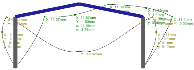
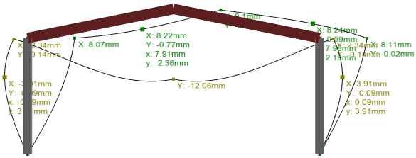
For example, in the following simple portal frame model, there is a vertical deflection at the apex of 18.52mm in load case 1 and a horizontal deflection at the knee of 11.4mm in load case 2. If we wanted to limit these deflections to 12mm vertically at the apex and 10mm horizontally at the knee then we could use the optimizer to do it with the smallest possible increase in total mass.
After starting the optimization tool, the first step is to click the "Add group" button at the bottom of the "Optimization Members" panel and then select the desired members. In this case we have selected the two columns as one group, followed by the two rafters as another group. Those two groups appear as separate lines in the panel below. We have put them into separate groups and have ticked the "Update Member Sizes as a Group" boxes so that the left and right columns have matching sizes, and similarly the left and right rafters stay matched. If we selected all columns and rafters together and ticked the "Update Member Sizes as a Group" box then all four members would finish up with the same size, or if we unticked the "Update ..." box then all four members could finish up with different sizes.
The "Scan Codes" fields have been left blank in this example because we have already ticked the "Optimized sections have the same shape type" option above which forces all the members to keep their original cross section shape. If we wanted to allow different section shapes to be introduced then we could click the "..." button in the "Scan Codes" field and then select other section shapes.
If you want to change or add to the selected members, you can click the "Select Members" button in the appropriate line of the panel and then select or deselect members graphically.
Node deflections
The next step is to select various control nodes and their target deflections that the optimizer will aim for.
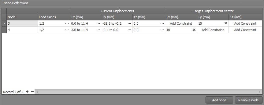
This can be done by clicking the "Add Node" button at the bottom of the "Node Deflections" panel and then selecting the desired node graphically. In this case we have selected node 3 (the apex node) followed by node 4 (the knee node) to have them both added to the panel.
We have also chosen to include both load cases 1 and 2 in the optimization, meaning that the deflection limits will be imposed for both load cases.
The "Current Displacements" columns show what the current deflections are in each direction for the load cases listed.
The "Target Displacement Vector" columns contain the target deflections and in this case we have entered 15mm vertically at node 3 and 10mm horizontally at node 4. If you want the target deflections to apply in just one direction then you should prefix them with a "+" or "-". For example, a target deflection of "+15" means that it would be limited to 15mm in the positive direction but there would be no limit in the negative direction. Similarly, "-10" would limit the negative deflection to 10mm with no limit on the positive deflection.
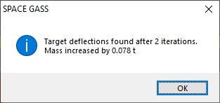
Optimization
It is then just a matter of clicking the main Ok button to begin the optimization process.
In this case it has achieved the target deflections after two iterations with a mass increase of just 78kg.
A graph is then displayed that shows the progress of the optimization. In this case, the process was quite linear with the deflection reductions of 3.5mm and 1.4mm achieved in only two iterations. The table on the left shows the change after each iteration.
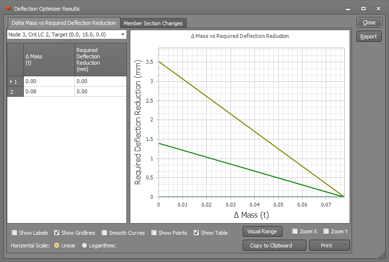
If you click the "Member Section Changes" tab at the top of the graph you can see which members were changed along with their new section sizes. In this case it shows that the rafters were increased from 250 UB 37,3 to 360 UB 44.7 and the columns were left unchanged.
The new final deflections are shown below and you can see that they are now within the targets of 10mm horizontally and 15mm vertically.
Note that the optimization settings are not saved and so if you close the deflection optimization tool then you will have to re-enter all of the optimization data. Future versions will retain the data with the job.