Plate spring supports
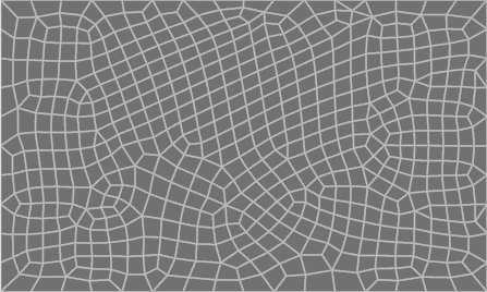
This tool calculates the spring stiffness of each node in a slab or footing that is supported on an elastic material such as soil. Because the meshing of the slab or footing generally results in elements of various shapes and sizes (as you can see in the image below), calculating the tributary area of each node in order to determine its spring stiffness is not straightforward, and so this tool is provided to automate the process.
Operating the tool involves selecting all the plate elements in the slab or footing, right-clicking and then selecting "Plate Tools" => "Generate Plate Spring Supports" from the popup menu that appears.
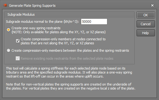
You should then specify the subgrade modulus of the soil. The spring stiffness is based on its tributary area multiplied by the specified subgrade modulus.
There are two options for how soil can be modelled using springs:
- Create one-way spring restraints: One-way springs are generated at each node location. This option is only available if the selected plates are along the XY, YZ or XZ planes. If the plates are along the XZ plane, the direction of the one-way spring is positive. Otherwise, the direction of each one-way spring restraint is based on the direction of the local z axis of the plates.
- Create compression-only members between the plates and the spring restraints: Spring supports are generated under each node and a compression-only member is inserted between each spring support and the slab or footing.
If it detects existing compression-only members or spring restraints attached to the selected plate nodes then it will give you the option to replace them.
If it detects existing other (non-compression-only) members attached to the selected plate nodes then it will give you the option to skip those locations so that no compression-only members or springs are added there.