Sea loads
This tool lets you generate wave, ocean current, marine growth and buoyancy loads on submerged structures in marine and offshore environments where these effects impose significant loading on the affected structure.
The procedure for load calculation starts with the analysis of the wave by an appropriate theory to determine the water particle velocities and accelerations at various depths in the water body. The computed velocities and accelerations are combined with any additional water current velocities (tidal, density current, storm velocity, etc), marine growth loads and buoyancy loads for determining the effective loading on individual structural elements. When combining wave and water currents the Doppler effect of the current on the wave is automatically taken into account.
Presently, Airy's linear wave theory and Stokes' 5th and 2nd order non-linear wave theories are incorporated into this tool. Sea loads on the structure comprising drag and inertia loading on individual structural members are computed using Morison's equation. The formulation applies strictly to skeletal framed structures with slender tubular members, but can also be applied to framed structures with non-tubular members applying modified coefficients for drag and inertia. The tool is not suitable for the computation of sea loads on large bodies such as vessels, ship-shaped or boxed and/or plate structures where the length to effective diameter ratio of any individual element is small.
The sea load generator uses the concept of "scenarios", each of which represents the motion of a wave and generates multiple load cases that correspond with the various positions of the wave. It is normal for a scenario to represent a full wavelength, however you can reduce it to part of a wavelength by changing the "Phase increment" and "Steps" variables so that their product is less than 360 degrees if desired.
The procedure is as follows:
- From within the renderer, select the members that are flooded, click the right mouse button and then select "Loads" => "Generate Sea Loads" from the popup menu that appears.
Note that all of the submerged members in your model will be loaded, regardless of whether you select them or not. The members you select will indicate which of them are to be regarded as "flooded". The unselected (non-flooded) members will be subjected to buoyancy loads if they are tubular, whereas the selected (flooded) members will not.
- In the sea load form that appears (as follows), change the data to suit your requirements and then click the Ok button.
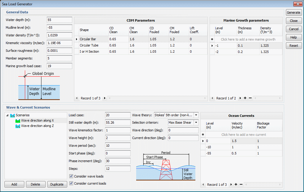
General Parameters:
The following parameters are general in nature and apply to all the sea load cases.
Water depth
This is the still water depth above the mudline (or seabed), excluding any tide or storm surge effects.
Mudline level
The mudline level is essentially the seabed level. It is the level relative to the global origin of the SPACE GASS model and is negative if the mudline is below the SPACE GASS origin (the normal situation).
It may be prudent to set up your model so that its origin is at the waterline and therefore Mudline level = - (Water depth). This also means that any "Levels" such as the mudline level, marine growth levels or ocean current levels would always be negative if below the waterline.
Water density
The normal density of water.
Kinematic viscosity
This varies with the water temperature. The default value is based on a water temperature of 15 deg C.
Surface roughness
The surface roughness affects the drag of the water on the structure. The surface roughness value you specify is only used on surfaces that have no marine growth. For surfaces that have marine growth the surface roughness is taken as the marine growth thickness up to a maximum of 50mm.
Member segments
The number of segments that a distributed load is broken into along a member to simulate the curved profile of the applied load.
Marine growth load case
This is the load case that the self weight of the marine growth will go into. Because marine growth doesn't change with waves or currents its self weight is put into its own load case. You can the combine it with the wave and current load cases using combination load cases in the normal way.
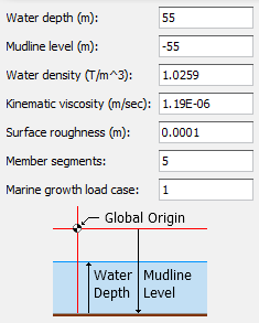
CDM parameters
These are the drag (CD), inertia (CM) and lift coefficients that are used in the sea load calculations on submerged members. Guidance for selection of these parameters is available in various code standards including API RP 2A. In the absence of any other information you could consider using CD=0.65 & CM=1.60 for clean tubular members or CD=1.05 & CM=1.20 for fouled tubular members. Values of CD and CM for other cross section types may be obtained from international codes and standards including DnV codes.
The "Smooth" coefficients are used if k/D <= 0.0001, the "Rough" coefficients are used if k/D >= 0.01 and an interpolation between the "Smooth" and "Rough" coefficients are used if 0.0001 < k/D < 0.0, where k is the surface roughness and D is the largest dimension or diameter of the member.
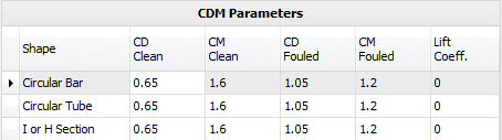
Marine growth parameters
Any structural element submerged in water will have marine growth developed on its wetted surfaces. Such growth effectively increases the element's exposed area to waves which in turn attracts higher wave loading. For this reason the marine growth parameters applicable to the region where the structure is located needs to be considered in the sea load analysis.
At least two lines of marine growth data are required, with the marine growth only occurring between the levels and not outside them. If the thickness or density is different in adjacent levels then they are assumed to vary linearly between the levels. Marine growth levels are relative to the SPACE GASS origin and are negative if the location is below the origin.
Scenarios
Each scenario represents the motion of a wave and normally covers a full wavelength. If the "Selection Criterion" is set to "None" then multiple load cases representing the various positions of the wave are generated for each scenario. If the "Selection Criterion" is set to "Maximum overturning moment" or "Maximum base shear" then only one load case will be generated for each scenario. You can specify multiple scenarios, each with its own direction and load case(s).
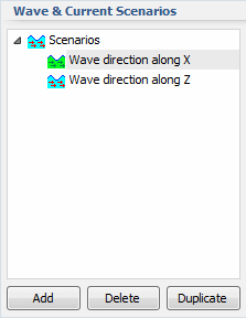
The following parameters are scenario specific.
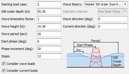
Load case / Starting load case
This is the first of the load cases that will be generated for the current scenario. If the “Selection Criterion” is set to “None” then the last load case for the scenario = Starting load case + Steps – 1, otherwise there is only one load case per scenario.
Still water depth
Is based on the general water depth, but also includes any tide and/or storm surge at the time of occurrence of waves. It cannot be less than the general water depth.
Wave kinematics factor
Guidance for selection of the wave kinematics factor is available in various code standards including API RP 2A. In the absence of any other information you could consider using 0.85 to 0.95 for extreme cyclonic or storm waves, or 1.00 for normal operating and fatigue waves.
Wave height
The wave height is the vertical distance between the wave crest and the trough.
Wave period
The wave period is the time it takes for the wave to travel through one wavelength (ie. the distance between consecutive wave crests) relative to a stationary point. The sea load output also reports the "Apparent Period", which is the wave period relative to a point travelling with the current (if a current exists). A current in the wave direction tends to stretch the wavelength and increases the apparent period, while an opposing current shortens them. This is the Doppler effect of the current on the wave.
Start phase and phase increment
Sea loading on a marine structure varies continuously as the wave passes through the structure with the maximum loading occurring at a specific position of the wave with respect to the structure. To determine the maximum loading, the wave is simulated to pass through the structure beginning with the start phase position and stepping the wave at the specified phase increment. A phase of 0 degrees corresponds with the wave crest at the origin (ie. the 0,0,0 position) of your model. 360 degrees is equivalent to one wavelength.
Steps
This is the number of phase increment steps considered during the analysis. End phase = Start phase + (Steps x Phase increment). If the “Selection Criterion” is set to “None” then the number of load cases generated for a scenario is equal to the number of steps, otherwise there is just one load case per scenario.
Wave theory
Selection of the wave theory for analysis of any wave depends on the wave parameters and the water depth. A general guidance for selection of the wave theory can be obtained from the American Petroleum Institute's Recommended Practice API RP 2A. In the absence of other information the following could be considered as a rough guideline:
if 0.000 <= H/(g.T^2) <= 0.001 and 0.01 <= d/(g.T^2) <= 0.2 then select Airy's linear theory
if 0.001 <= H/(g.T^2) <= 0.02 and 0.005 <= d/(g.T^2) <= 0.2 then select Stokes' 5th Order non-linear theory
where H = wave height, d = still water depth, T = wave period and g = gravitational acceleration.
Selection criterion
Sea loading on the structure is evaluated at each position of the wave as it passes through the structure and, depending on the "Selection criterion" specified in the form, the critical position is selected as the position of the wave that results in the maximum base shear or the maximum overturning moment at the mudline. If set to "None" then a load case is generated at each wave position and no attempt is made to determine the critical one.
Note that the base shear and overturning moment calculations are based on the horizontal wave and current loads only and exclude any vertical loads from buoyancy, self weight, marine growth or other applied loads.
Wave and current direction
These are the directions of the approaching wave and water current relative to the global X-axis. Direction angles are positive anti-clockwise from global X when viewed in plan.
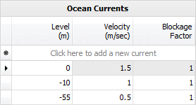
Ocean currents
Currents occurring simultaneously with waves significantly influence the total sea loading and need to be considered in the analysis. Current profiles should be input for each scenario. They are combined with the wave velocities determined by the wave analysis before Morison's equation is applied.
At least two lines of ocean current data are required, with the currents only occurring between the levels and not outside them. If the current is different in adjacent levels then it is assumed to vary linearly between the levels. Ocean current levels are relative to the SPACE GASS origin and are negative if the location is below the origin.
The "Blockage Factor" controls how much the current stream in the vicinity of the structure is reduced from the specified "free stream" value by blockage. In other words, the presence of the structure causes the incident flow to diverge. Some of the incident flow goes around the structure rather than through it, and the current speed within the structure is reduced. Blockage factors ranging from 0.7 to 1.0 are typical, with 1.0 representing no blockage.
Doppler effect
When waves and currents occur together, an "Apparent Period" relative to the current is determined, accounting for the Doppler effect of the current on the wave. A current in the wave direction tends to stretch the wavelength and increases the apparent period, while an opposing current shortens them. The apparent wave period is determined from API RP 2A Figure 2.3.1-2 if -0.015 <= V/gT <= 0.025, where V is the current component in the wave direction, g is the acceleration due to gravity and T is the actual wave period relative to a stationary point. If V/gT is outside of the above mentioned limits then a warning is issued and the results may not be accurate.