Subdivide
The Subdivide tool allows you to select one or more members and subdivide them by inserting intermediate nodes at regular or irregular positions along them.
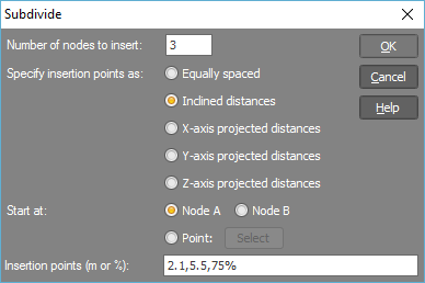
After selecting the members to be subdivided, right-click and select "Member Tools" => "Subdivide" from the popup menu that appears. You should then specify the number of subdivisions and their spacing in the form shown below.
If the node insertion points are irregular, you can nominate "Insertion points" to be expressed as inclined distances, or as projected distances along one of the global axis directions. Naturally, you cannot nominate projected distances along
a global axis which is at right angles to the axis of the member being subdivided.
Insertion points are referenced from the node A end or Node B of the members. They can be expressed as actual distances or as percentages. For example, to subdivide a 10m beam into 2m, 3m, and 5m beams, you could type 2,5,
or 2,50%, or 20%,50% into the "Insertion points" field. In all three cases, the final result is the same.
If you are using percentages for all of the insertion points, then the inclined or projected axis specification is irrelevant.

Subdividing relative to an external point
If you wish to subdivide members relative to a point external to the members then you should choose the "Point" option, click the "Select" button and then select the point to subdivide from. This point can be a node or any point in space. For example, if you have a model in which you want to subdivide all the columns at a level that is 5.5m from the ground, you could select all the columns and then from within the subdivide tool, choose "Y-axis projected distances" (assuming Y is vertical), choose the "Point" option and select a point that is at ground level.
