Varying member distributed loads
This tool allows you to apply distributed loads to a group of members based on a linear or equation based load distribution that you specify. It doesn't matter if the members are subdivided or not.
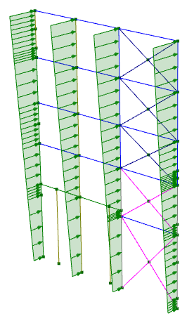
In the following example we have a frame containing columns that we want to apply distributed loads to with a load of 0.55kN/m at the bottom varying linearly to 1.35kN/m at the top. It doesn't matter that the columns have various subdivisions and intermediate connections to other members.
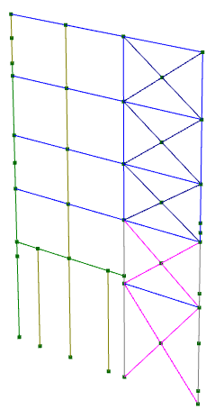
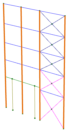
We start by selecting the members to be loaded.
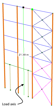
Followed by right-clicking and selecting "Member Loads" => "Varying Distributed Loads" from the popup menu. We can then draw a "load axis" that defines the relative position and length of the distributed loads about to be applied. In this case we have just drawn it in the plane of the frame with the same vertical position and length as the columns to be loaded. The lateral position of each member relative to the load axis is not important and we could have just as easily drawn the load axis over one of the columns or some horizontal distance away from the plane of the columns for the same result.
.
In the following form that appears we can then define the load axes (local, global-inclined or global-projected), the direction vector of the loads and the linear or equation based load distribution.
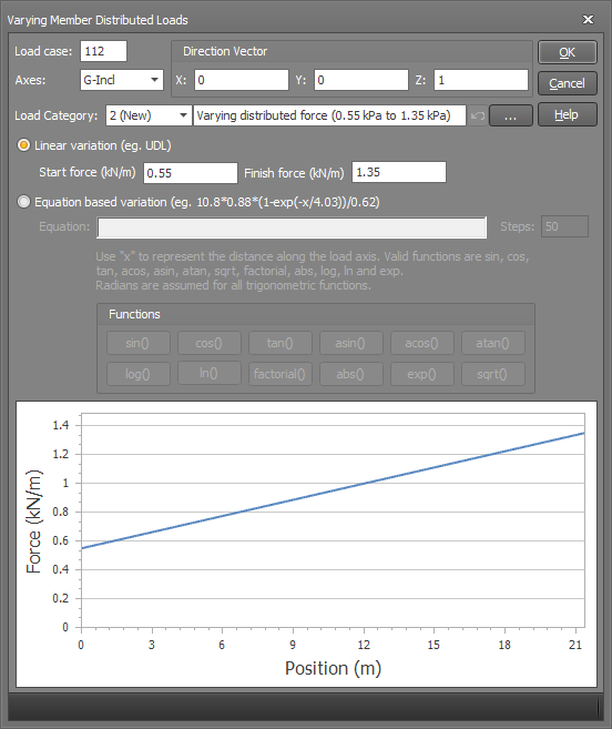
After clicking Ok, the distributed loads are calculated and projected normal to the load axis onto each member that you have selected. The portion of members that project beyond the ends of the load axis are not loaded. For example, if the load axis was drawn from the bottom to half-way up the columns then only the bottom half of the columns would be loaded.
See also Load contiguous members.