Coordinate systems
The geometry of a structural model is referenced by a set of global XYZ axes. Each member and plate element also has its own set of local xyz axes so that items such as section properties and local loads can be more easily referenced.
All axes are right hand orthogonal. This means that if you are looking at the XY plane with the Y-axis pointing upwards and the X-axis pointing to the right, the Z-axis points towards you as shown below.
Global Axes
The shape and position of a structure in space is defined by a set of global axes (X,Y,Z). All node coordinates, for example, are input relative to the global axes system. The global XZ plane is assumed to be horizontal, while the global Y-axis points vertically upwards.
Note that although SPACE GASS assumes that the Y-axis is vertical by default, it can be configured for the Z-axis vertical via the "Vertical Axis" setting. The logic behind having Y vertical is due to the fact that most 2D structural models are vertical and in the XY-plane, and so it seems logical to keep Y as vertical when the model is extended to 3D. If Y is vertical then any sloping members in SPACE GASS are by default aligned in a vertical plane.
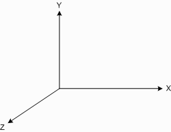
Global Axes
Member Axes
The local axes for a member have their origin at node A and are defined as follows:
-
The x-axis lies along the axis of the member and points from node A to node B.
-
The local y-axis is normal to the local x-axis and points in the same general direction as the global Y-axis. It is orientated such that the local xy-plane is parallel to the global Y-axis.
-
The local z-axis is orthogonal with x and y.
For members that have their longitudinal axis parallel to the global Y-axis, rule 2 is undefined and hence, for these members, the local z-axis points in the same direction as the global Z-axis.
-
If a direction angle, node or axis is defined then the member is rolled about it’s longitudinal x-axis by the direction angle or, if a direction node or axis is defined, by an amount such that the local y-axis is aligned with the direction node or axis as shown below.
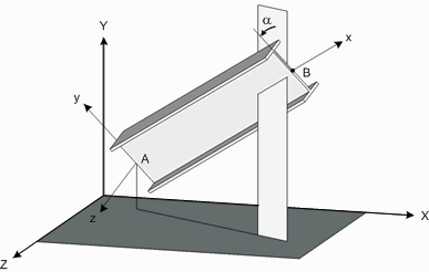
Member Local Axes
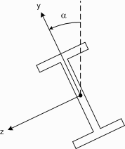
Member Direction Angle
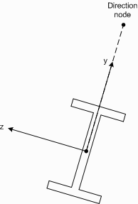
Member Direction Node
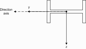
Member Direction Axis
If you are unsure of the orientation of the local axes for a particular member, you can display them graphically (see also View local axes).
Plate Axes
The local axes for a plate have their origin at the centre of the plate and are defined as follows:
-
The x-axis is in the plane of the plate and is parallel to the line joining node A and node B.
-
The local y-axis is also in the plane of the plate and is normal to the local x-axis.
-
The local z-axis is normal to the plane of the plate and is orthogonal with x and y.
-
If a direction angle, node or axis is defined then the local axes are rotated about the plate’s normal z-axis by the direction angle or, if a direction node or axis is defined, by an amount such that the local y-axis is aligned with the direction node or axis as shown below.
Note that defining a direction angle, node or axis affects the orientation of the plate’s axes but not the orientation of the plate itself.

Plate Local Axes
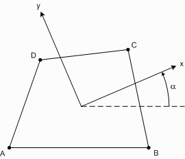
Plate Direction Angle
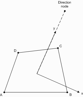
Plate Direction Node
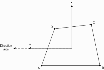
Plate Direction Axis
If you are unsure of the orientation of the local axes for a particular plate, you can display them graphically (see also View local axes).