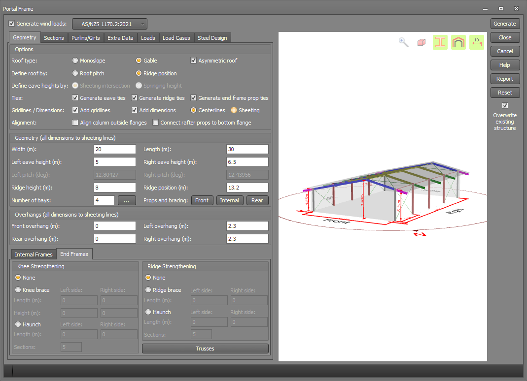
Portal frame geometry
This form lets you define the basic geometry of the portal frame building.
Definitions of Front, Left, Rear and Right Walls
The walls of the building are defined as front, left, rear and right respectively when viewed from above in clockwise order, with the front and rear walls being normal to the ridge line. The orientation of the building (if known) is defined by the bearing of a vector along the ridge line pointing from the rear of the building towards the front. For example, a building with a bearing of 0 degrees would have its front wall facing north and its left wall facing east, whereas a bearing of 90 degrees would correspond to the front wall facing east and the left wall facing south.
Options
The basic options are largely self-explanatory, however some of the less obvious ones are explained in more detail below.
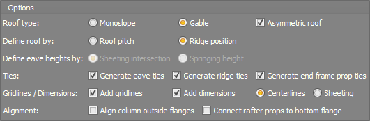
If "Define eaves height by" is set to "Sheeting intersection" then the height is measured from the footing to the intersection point of the wall and roof sheeting. Otherwise it is measured to the "Springing height", which is the underside of the rafter (or haunch if one exists) at the face of the column.
Eave and ridge ties are extended down the full length of the building, whereas end frame prop ties are placed just between the end frame and the first internal frame at each end of the building wherever there is a prop.
Gridlines and dimensions can be generated automatically if ticked. You can also edit them or add extra dimensions manually using the normal gridline and dimensioning tools.
If you tick "Align column outside flanges" and the end frame columns are different to the internal frames then the columns will be adjusted so that their outside flanges line up down the length of the building. If unticked, the columns will be aligned via their centroids.
The "Connect rafter props to bottom flange" option lets you decide between connecting the props to the rafter centerline or to the bottom flange. If connected to the centerline the connection is pin-ended, whereas if connected to the bottom flange the connection is rigid. The reason for the rigid connection is to prevent shear force in the prop generating torsion in the rafter and potentially causing it to fail unrealistically.
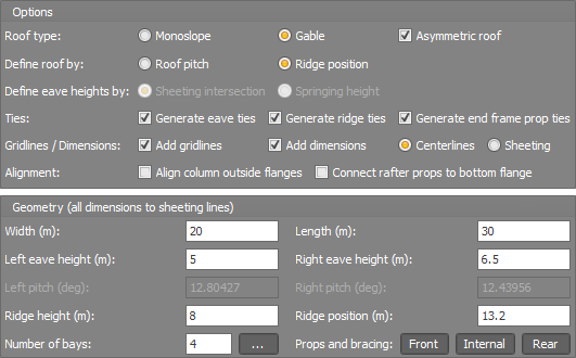
Geometry
All dimensions in the geometry fields are relative to the sheeting lines. The only exception to this is if the "Springing height" is selected, in which case the eave heights are measured to the springing height.
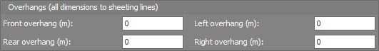
Overhangs
Overhangs can be specified for any of the four sides of the building. The wind pressure coefficient on overhangs is taken to be the same as the adjacent wall for the underside of overhangs and the same as the adjacent roof section for the topside of overhangs. For IS875 the pressure coefficient for the underside of overhangs on the windward side can be different to the adjacent wall. It is taken as 1.25 if the overhang slopes downwards, 1.0 if it is horizontal or 0.75 if it slopes upwards as per IS875 clause 7.3.3.5.
Note that the portal frame builder assumes that overhangs are relatively small, and doesn't consider any of the more specialized wind loading rules that apply to canopies, awnings or cantilevered roofs.
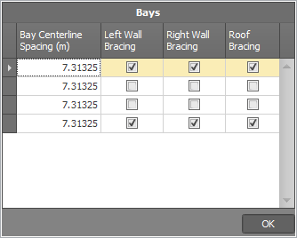
Frame spacing, side wall bracing and lateral roof bracing
The frames are assumed to be equally spaced with the end bays braced by default, but you can change the spacing and/or bracing by clicking the  button next
to the number of bays field. The frame spacing values are measured to the column centroids and could affect the overall length of the building if you change them.
button next
to the number of bays field. The frame spacing values are measured to the column centroids and could affect the overall length of the building if you change them.
Note that if you make the frame spacing unequal then changing the building length or the number of bays will reset the frames back to equally spaced.
Rafter props, end wall bracing and longitudinal roof bracing
You can get access to the end frame rafter props, end wall bracing and longitudinal roof bracing via the  buttons.
Prop positions are measured relative to the column centerlines and can be specified in actual distances or as a percentage of the frame width. After entering the prop positions for a particular frame you can then copy them to other frames by clicking the "Copy to..." button at the bottom of the table.
For internal props, the "Prop direction" field controls the direction of the local y-axis (or minor axis) of the prop. For example, if you specify "Front" then the prop's y-axis will point towards the front of the building and its minor axis will be aligned with the building's ridge, whereas if you specify "Left" then the prop's minor axis will be normal to the ridge.
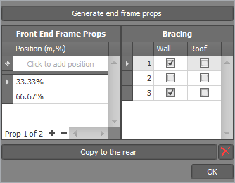
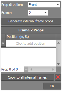
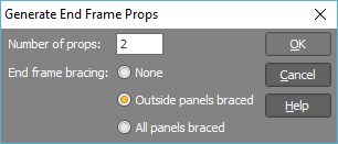
If the props are equally spaced then instead of entering them in the table you can click the "Generate..." button at the top and then specify how many props are required.
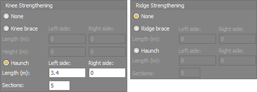
Knee or ridge strengthening
Braces or haunches can be applied to the knees or ridge to strengthen them. These can be specified differently for the end and internal frames.