Shape builder
You can open the shape builder by clicking the ![]() button in the Member Properties panel.
button in the Member Properties panel.
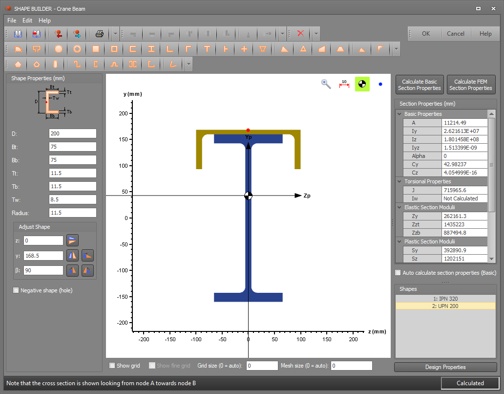
The shape builder allows you to modify library shapes, combine library, standard and custom shapes into built-up sections, and create standard and custom shapes. Standard shapes are easily created by clicking on one of the standard shapes buttons and entering the desired dimensions. For a custom shape, you are required to enter three or more coordinates and the shape builder will display the shape and calculate the section properties.
Inputting shapes
To input a shape, you can:
-
Import it from a sections library by clicking the library button
 .
. -
Import it from a DXF file by clicking the import DXF button
 .
. -
Click the points shape button
 and then enter a set of coordinates to define the perimeter of a shape.
 -
Click the line shape button
 and then enter a set of coordinates to define a shape formed by a line of a user defined thickness.
 -
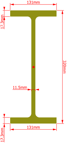
Click one of the standard shape buttons and then enter its dimensions.

Any shape (other than a hollow shape) can be converted to a negative shape (void) by ticking the "Negative shape (hole)" option. This makes it very easy to model voids in your cross section.

Editing and combining shapes
You can input up to 10 shapes from any of the above sources and combine them to form your desired cross section.
Each shape can be translated, mirrored, rotated or transposed using the shape editing buttons shown below.

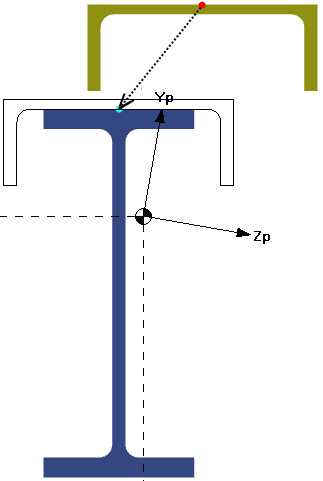
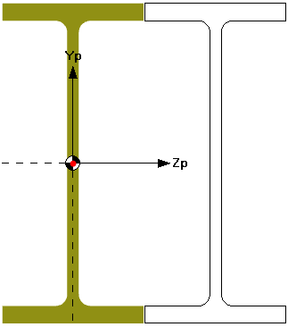
Shapes can also be dragged and snapped together via their edge and corner reference points as shown below.
When dragging shapes, the behaviour can be controlled using the grid and snap settings along the bottom of the shape builder as shown below.
![]()
Shapes can be copied by dragging while holding down the Ctrl key.
Multiple shapes can be selected by clicking them while holding down the Shift key. You can then use the alignment buttons 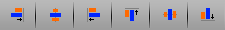 at the top of the shape builder
to align the selected shapes along the top, bottom, center, left or right. Alternatively, you can stack shapes vertically or horizontally using the stack alignment buttons
at the top of the shape builder
to align the selected shapes along the top, bottom, center, left or right. Alternatively, you can stack shapes vertically or horizontally using the stack alignment buttons  .
.
Dimensions
Dimensions can be added to shapes by clicking the dimensions button  .
.
Section property calculations
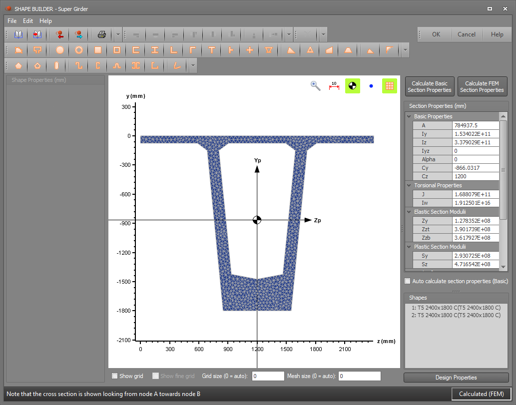
Torsional and shear properties can now be calculated using a finite element method based on theory by Walter Pilkey, 'Analysis and design of elastic beams:. Computational Methods'. The FEM provides a more accurate but slower method of calculating these properties than the basic property calculation method. The FEM can calculate the properties of multiple shapes provided they are touching as part of an edge, not a corner/point. The finite element mesh used for the calculation can be viewed and mesh size adjusted if a more refined calculation is required.
The basic calculation method is a much quicker calculation method but for non-standard shapes the torsional and shear properties are approximated or not calculated.
![]() The FEM calculated properties cannot be saved to a section library.
The FEM calculated properties cannot be saved to a section library.

Design properties
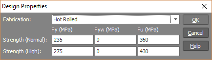
SPACE GASS can now do a steel member design or check using sections that haven't been imported from a library, however you must specify their steel design properties. You can do this via the shape builder "Design Properties" button. Generally speaking, you would only use the "Design Properties" button when are you don't want to save the section to a library because the saving to library process also includes inputting the steel design properties.
Saving sections
You can save your section to a custom library for later recall into any other jobs by clicking the "Save to Library" button ![]() and then filling out the form that appears below.
and then filling out the form that appears below.
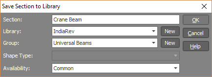
If a custom section library doesn’t yet exist or if you wish to create a new custom library, click the ![]() button at the right of the
"Library" field and then fill out the custom library’s details. Similarly, if the library doesn’t yet contain any groups or if you wish to create a new group within a custom library, click the
button at the right of the
"Library" field and then fill out the custom library’s details. Similarly, if the library doesn’t yet contain any groups or if you wish to create a new group within a custom library, click the ![]() button at the right of the "Group" field and then fill out the group’s details.
button at the right of the "Group" field and then fill out the group’s details.
![]() The SPACE GASS section libraries can now contain
built-up sections made from whatever shapes you can build in the shape builder, including voids. Built-up, non-standard, mirrored or rotated sections cannot be used in the design/check modules, however they can be used in a static, dynamic or buckling
analysis.
The SPACE GASS section libraries can now contain
built-up sections made from whatever shapes you can build in the shape builder, including voids. Built-up, non-standard, mirrored or rotated sections cannot be used in the design/check modules, however they can be used in a static, dynamic or buckling
analysis.
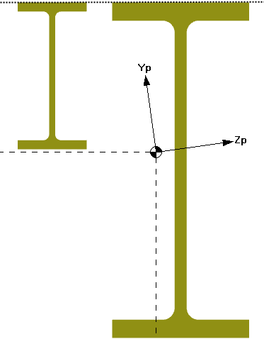
![]() The shape builder always shows the cross section as if you are looking along the member from
node A towards node B. This is the reverse of how it was in SPACE GASS 10 and earlier versions.
The shape builder always shows the cross section as if you are looking along the member from
node A towards node B. This is the reverse of how it was in SPACE GASS 10 and earlier versions.
![]() The section properties displayed in the panel on the right side of the shape builder apply
to the whole cross section (ie. the sum of the composite shapes in the display window).
The section properties displayed in the panel on the right side of the shape builder apply
to the whole cross section (ie. the sum of the composite shapes in the display window).