Flange restraints
Flange restraints must be specified for both top and bottom flanges at each end of a design group and at each intermediate restraint position.
Because the positions of the start and finish flange restraints is known, only the intermediate restraint positions should be specified. However, the end and intermediate restraint types should be specified.
The top flange of a member is the flange on the positive local y-axis (or z-axis if the section has been flipped) side of the member. The top flange of a group as a whole is defined such that it is the same as the top flange of the first member in the group.
You can verify graphically which is the top flange by clicking the ![]() button near the bottom of the side toolbar. It displays a small triangle that points to the top flange of each member.
button near the bottom of the side toolbar. It displays a small triangle that points to the top flange of each member.
There are two classes of restraint types; those that occur at a discrete point and those that occur over a continuous length of flange between two point restraints. The number of point restraint types should exactly match the number of restraint positions.
When @ multipliers are used in the restraint positions lists, the corresponding restraint types must have only one character for each @ multiplier. For example, restraint positions of 1.2,2.4,3.6,4.8,6.0,6.6,7.2,7.8,8.4 with corresponding restraint types of LLLLLPPPP could be specified as 5@1.2,4@0.6 and LP. If the restraint types were LLPLLPPPP, however then they would have to be specified as 2@1.2,3.6,2@1.2,4@0.6 and LPLP.
SPACE GASS accepts six point flange restraint types and two continuous flange restraint types. They are defined as follows. Note that these definitions are slightly different to the ones in the design codes because the code definitions apply to the cross section rather than to each flange. The cross section restraints are determined from the flange restraints during the design or check phase.
|
Full restraint (F) |
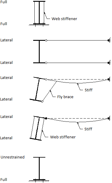
Prevents lateral deflection of the flange to which it is applied and fully prevents twist rotation of the section. |
|
|
|
|
Partial restraint (P) |
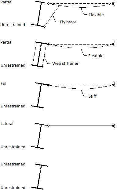
Prevents lateral deflection of the flange to which it is applied and partially prevents twist rotation of the section. |
|
|
|
|
Lateral restraint (L) |
Prevents lateral deflection of the flange to which it is applied but is ineffective in preventing twist rotation of the section. A lateral restraint can only be considered to be effective when it is positioned between full or partial restraints. |
|
|
|
|
Full & rotational restraint (R) |
The same as full restraint above but also with significant restraint against lateral rotation of the flange about the cross section’s minor axis. |
|
|
|
|
Partial & rotational restraint (S) |
The same as partial restraint above but also with significant restraint against lateral rotation of the flange about the cross section’s minor axis. |
|
|
|
|
Unrestrained (U) |
There is no resistance to lateral deflection of the flange to which it is applied or twist rotation of the section. This can only be used at the end of a design group. |
![]() An "unrestrained" end does not necessarily imply a cantilever. Flange restraints are independent of the member support system. Cantilevers or beams with supported ends could be restrained or unrestrained.
An "unrestrained" end does not necessarily imply a cantilever. Flange restraints are independent of the member support system. Cantilevers or beams with supported ends could be restrained or unrestrained.
The following flange restraint types do not occur at a point but are continuous between two adjacent point flange restraints.
|
Continuous lateral restraint (C) |
Prevents lateral deflection of the flange to which it is applied but is ineffective in preventing twist rotation of the section. A continuous lateral restraint can only be considered to be effective when it is positioned between full or partial restraints. |
|
|
|
|
Ignore segment (I) |
This is not really a flange restraint, rather it instructs SPACE GASS to skip past the ignored segment length when designing or checking. It can be used very conveniently to ignore the very rigid area where intersecting members connect so that members are designed from the face of intersecting members rather than from their centrelines. It is also very handy for when a member is stiffened over part of its length and is not required to be designed over that portion. |
The above definitions allow for full, partial, lateral or no restraint against twist of the cross section (about its longitudinal axis) (F,P,L,C or U). They also allow for full or no restraint against lateral rotation of the critical flange (about the minor cross section axis) in the presence of full or partial twist restraint (R or S). An extra restraint condition which is catered for in AS1250, SABS0162, BS5950, AS3990 and HK CP2011 only, that provides partial restraint against lateral rotation of the critical flange is not supported by SPACE GASS.
![]() For single angle sections, it is unclear whether or not lateral restraints applied to either leg are effective in providing any restraint to the section. Consequently, you should be very careful when applying lateral restraints to single angle sections and you should use them only if you are sure they are effective in restraining the section. SPACE GASS will apply them if you specify them and so the decision about whether or not they should be used is entirely up to you.
For single angle sections, it is unclear whether or not lateral restraints applied to either leg are effective in providing any restraint to the section. Consequently, you should be very careful when applying lateral restraints to single angle sections and you should use them only if you are sure they are effective in restraining the section. SPACE GASS will apply them if you specify them and so the decision about whether or not they should be used is entirely up to you.
Note that the design/check calculations are based on the effective cross section restraint rather than the restraint on a particular flange. The effective cross section restraint depends on which flange is the critical one and on what flange restraints are applied to the critical and the non-critical flanges. Refer to "Effective flange restraints" for more information.
The following diagrams are a collection of some fairly typical support and fly brace connection details. The type of restraint that applies to each flange is shown as either "full", "partial", "lateral" or "unrestrained". Note that the diagrams apply regardless of whether or not rotational restraints also exists. The terms "full" or "partial" could also read "full and rotational" or "partial and rotational" in each of the diagrams.


Flange restraint types
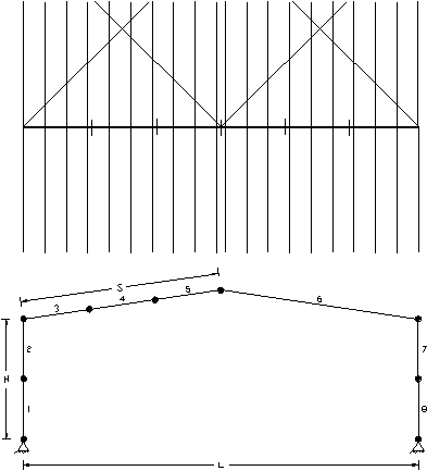
Consider, for example, the portal frame below. The roof bracing system laterally braces each rafter at the eaves and apex. Purlins are positioned at ninth points along each rafter and fly braces are attached to each third purlin at rafter third points. Girts are positioned at the mid-height of each column.

Portal frame flange restraints
We will assume that the roof sheeting has enough rigidity to allow the purlins to prevent lateral deflection of the rafter top flange. Note that if the roof sheeting has insufficient rigidity to prevent lateral deflection then the fly braces will not be capable of providing any restraint to the bottom flange and will thus be totally ineffective.
The frame could be set up with four design groups, each containing the following members.
|
Group 1: |
1,2 |
|
Group 3: |
3,4,5 |
|
Group 6: |
6 |
|
Group 7: |
7,8 |
When determining flange restraint positions and types, we will assume that the footing, eave and apex connections provide F (full) restraint to both flanges of each member framing into them.
There is no fly bracing attached to the wall girts and they provide lateral restraint only to the outside flange of the columns. Thus, groups 1 and 7 have top flange restraints of F (full) at each end and L (lateral) at mid height, and bottom flange restraints of F (full) at each end only. If there had been fly bracing to the girts then there would also be a bottom flange mid height restraint of L (lateral). Note that the top flange for groups 1 and 7 is the outside flange because the local y-axis for members 1, 2, 7 and 8 points towards the outside of the frame.
Similarly, groups 3 and 6 have top flange restraints of F (full) at each end and L (lateral) at each purlin, and bottom flange restraints of F (full) at each end and L (lateral) at each fly brace location. Thus, the restraint arrangements for the frame are:
|
Groups 1 and 7: |
FLF |
(Outside flange) |
|
|
FF |
(Inside flange) |
|
Groups 3 and 6: |
FLLLLLLLLF |
(Top flange) |
|
|
FLLF |
(Bottom flange) |
Note that by applying L (lateral) restraints to both flanges at each fly brace location we are assuming that the purlins are flexurally stiff enough to fully prevent twist rotation of the rafter. If they can only partially prevent twist rotation of the rafter then the group 3 and 6 restraints would become FLLPLLPLLF on the top flange and FF on the bottom flange.
Restraint Forces
The brace, purlin, girt or other member that provides full, partial or lateral restraint to the critical flange of a member must be capable of resisting the force required to provide such restraint. This is not automatically allowed for in the analysis or design. If you wish to take this into account then you should add the restraint forces to your applied loads. The restraint forces are code specific and you should refer to the appropriate clauses for the design code you are using.
This effect is particularly important for deep beams where the forces required to restrain the critical flange can be quite high. You should check that your model is capable of withstanding these forces.