Steel member input form
This tool allows you to graphically define and edit steel design members (also known as "design groups"). Note that multiple steel design members can be defined in a single operation using the "Auto-create steel members" tool.
You can access the steel member input form by selecting "Steel Member Design Input-Graphical" from the Design menu or selecting some members and then "Steel Member Design Input (Form)" from the popup menu.
It is recommended that you initially generate all the steel design members using the "Auto-create steel members" tool and then check and edit them on an individual basis using the procedure described here.
Each steel design member contains one or more analysis members connected end-to-end. After you have selected the analysis members that you wish to include in a steel design member, click the right mouse button and select "Steel Member Design Input (Form)" from the popup menu (or select "Ok" if you initiated the operation from the menu).
Because the top flange for a steel design group is taken to be the same as the top flange for the first member in the design group, it is important to be able to control which member comes first in the design group. Flange restraint positions are also referenced from the end of the first member in the design group.
If you are inputting a new design group, the member that you select first will be placed first in the design group (assuming that it is at either end of the group). If you want to select a "first" member, you should pick it directly or ensure that it is the only member selected if you use a window.
If you use a window and select a group of members initially, then the end one with the lowest member number will be placed first in the design group.
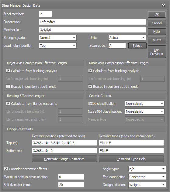
In the steel member form that appears, type in the data for the selected design group, and then click the form Ok button.
For detailed information about the data in the form, refer to "Steel member design data".
"Use Previous" button
Click the "Use Previous" button to set all the data in the form to the same as when the form was previously used.
You can show the steel design members graphically by clicking the ![]() button near the bottom of the side toolbar. They show up as thickened lines that are drawn slightly shorter than their actual length so that you can easily see where they start and finish.
button near the bottom of the side toolbar. They show up as thickened lines that are drawn slightly shorter than their actual length so that you can easily see where they start and finish.
You can also show the flange restraints graphically by clicking the ![]() button near the bottom of the side toolbar. It enables you to see exactly where the flange restraints are and whether they are on the correct flange or not.
button near the bottom of the side toolbar. It enables you to see exactly where the flange restraints are and whether they are on the correct flange or not.
For an overview of the various methods available for inputting steel member design data, refer to "Steel member input methods".