Using datasheets
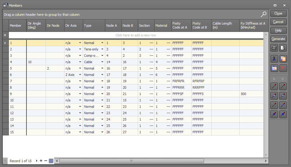
All datasheets have the same format, appearing in a grid format like a spreadsheet. The members datasheet is shown below.
Common datasheet operations
|
Sorting the data on any column
|
Click the column heading to sort on. Further clicks cause the sorting to alternate between ascending and descending order.
|
|
Frozen key columns
|
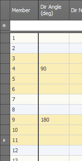
Allows you to scroll the main data sideways without scrolling the key columns so that you can always see which row you are working on. In the members datasheet, the "Member" column is the key column.
You can toggle the freeze line on or off using the
|
|
Multi-row editing
|
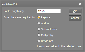
Possibly one of the most useful datasheet editing tools! It allows you to edit multiple rows of data simultaneously. The procedure is as follows:
|
|
|
Click the find icon, type the text to search for and then click the "Find" button to search for the text anywhere in the datasheet.
|
|
Grouping
|
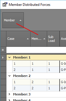
Drag a column heading button upwards to group the datasheet by that column. Drag additional buttons upwards to group in multiple levels.
Right click on any of the grouped buttons and select "Clear Grouping" to cancel the grouping and put the datasheet back to normal.
|
|
Editing existing data
|
Move to the desired cell using the keyboard or mouse and then type in or select the desired data.
|
|
Entering new data
|
Move to the top (blank) row and then type in or select the desired data.
|
|
Uniformly distributed loads
|
After entering the start load magnitude for a new load in a distributed load datasheet, the finish load magnitude is automatically set to the same as the start load, saving you having to enter the load magnitude twice for uniformly distributed loads. For existing loads this doesn't happen because the datasheet assumes that you are trying to specify a trapezoidal load. You can, however, make it happen when editing existing loads by typing into the start load cell as normal and then pressing the "F" key to "Fill" the finish load cell with the same value as the start load.
|
|
Combo boxes
|
To edit combo box cells, either click the arrow and then make your selection or just use the keyboard arrow keys to move to the combo box cell and then type the first character of the desired selection. For example, to change a Yes/No combo box to Yes, just move to the cell and then type Y.
|
|
Selecting rows
|
Click the button to the left of the row to be selected. You can select multiple rows by:
Alternatively, you can click the blank button at the top-left corner of the datasheet to select all the rows.
|
|
Cutting, copying and pasting
|
Cut or copy selected rows from a datasheet to any other Windows program or paste from another Windows program into a datasheet.
|
|
Duplicating rows
|
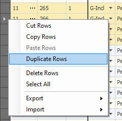
Rows of data can be duplicated using the normal copy and paste methods, however some datasheets such as section properties contain hidden fields that would not be duplicated using these methods. For example, all the geometric data for shape builder sections is stored in hidden fields. To ensure that the hidden fields are duplicated the following procedure can be used:
The duplicate rows will be inserted into the datasheet.
|
|
Deleting rows
|
Select the rows to be deleted and then press the Delete key or click the datasheet’s delete button or click the right mouse button and select Delete from the menu that appears.
|
|
Special buttons
|
Special buttons on some of the datasheets allow you to quickly change specific data in the current row. For example, the special fixity buttons in the members datasheet (shown left) let you choose commonly used fixity codes without having to type them in.
|
|
Counter
|
A counter at the bottom-left corner of the datasheet tells you how many rows of data are in the datasheet and which row is currently selected.
|
|
Generation
|
The generate button on some datasheets allows you to generate a number of extra items (members, nodes, etc.).
When you click the generate button you will be presented with a generation form which varies for each type of input. Most of the generation forms are self-explanatory, however some of them employ 2nd order generation which is explained below.
Note that it is often better and more convenient to use the graphical Copy tool for generating data rather than using the datasheet generate buttons.
|
Datasheet lookups
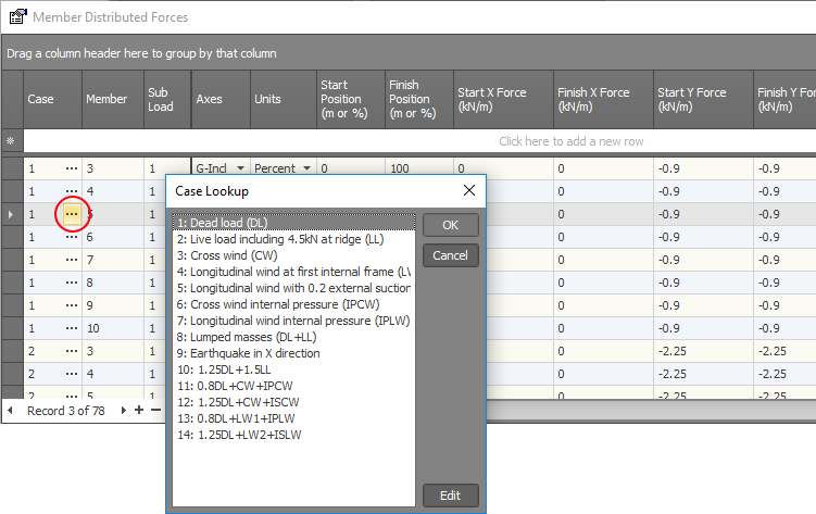
Some datasheet cells contain a  lookup button that allows you to select from a list of items. These are available for easy selection of load cases,
section properties, material properties and load categories.
Generation
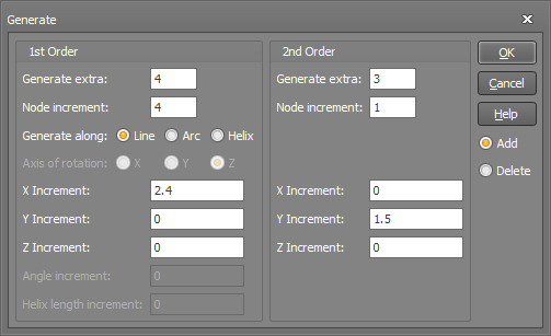
The above node generation form allows you to generate items along two axes at once. It can also be used to generate extra series at different levels (ie. the 2nd order).
Consider the following 20 node grid in the XY plane. It could have been created by inputting the coordinates for node 1 then generating four 1st order nodes (5,9,13 & 17) along a line with a node increment of 4 and X increment of 2.4, followed by three 2nd order rows of nodes with a node increment of 1 and a Y increment of 1.5.
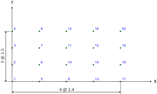
Grid of generated nodes
If only 1st order generation is required, you should specify zero for the number of 2nd order items to be generated.
The node generation form also has the unique ability to generate nodes along a line, arc or helix.
The axis of rotation, which only applies to an arc or helix, defines the point about which the nodes will be generated. The angle increment causes the nodes to be generated at some regular angle increment.
The helix length increment defines a regular increment along a parametric path at which the nodes will be generated.
2nd order generation is also employed in the member and member concentrated load datasheets.
Renumbering data
Any data can be renumbered by simply changing its number in a datasheet. However, be careful, because other related data in the model will not be automatically renumbered to match. A better way to renumber nodes, members or plates is to use the graphics renumber tool. It not only lets you renumber large groups of nodes, members and plates effortlessly, it also adjusts all of the restraints, constraints, loads, and design data automatically to allow for the new numbering sequence (see also Renumber).
![]() A convenient way to quickly move around and edit numeric cells in a datasheet is to use the keyboard arrow keys to move
to the desired cell, type the new data, then use the keyboard arrow keys to move to the next cell. You do not have to press ENTER to accept the new data.
A convenient way to quickly move around and edit numeric cells in a datasheet is to use the keyboard arrow keys to move
to the desired cell, type the new data, then use the keyboard arrow keys to move to the next cell. You do not have to press ENTER to accept the new data.
! IMPORTANT NOTE !
When you use a datasheet to renumber items, none of the other data which may reference the renumbered items is adjusted. You must do this yourself or use the renumber tool instead (as explained above).
See also Analysis data.
See also Steel member design data.
See also Steel connection design data.
 button at the bottom.