Align members
It is easy to align or stack members using the member alignment tools. The tools are "Align Members using Rigid Offsets" and "Face Alignment using Rigid Offsets".
As these tools align members using rigid offsets, the changes are not just cosmetic. These rigid elements can change the forces and moments in the member. For more information refer to "Modelling member offsets".
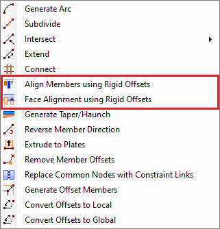
Align Members using Rigid Offsets
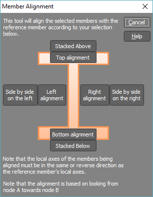
After selecting the members to be adjusted, right-click and select "Member Tools" => "Align Members using Rigid Offsets" from the popup menu that appears and then click another member to align them with. In the form that appears you can then choose to align the members according to their tops, bottoms or sides. Alternatively, you can stack members side by side or on top of one another using the "Stack" options.
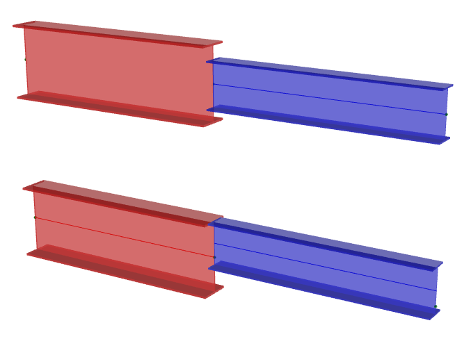
In the before and after diagrams below, the blue beam has been adjusted to align with the red beam's top flange.
Face Alignment using Rigid Offsets
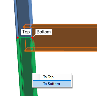
This tool effectively changes the length of a member to align it with the face of an intersecting member. To use this tool, first select the member to be aligned, then right-click and select "Member Tools" => "Face Alignment using Rigid Offsets". This will prompt you to select the intersecting member, and location on the intersecting member to align with. The end of a member can be aligned with the top, bottom, or either side of an intersecting member.
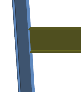
In the diagrams below, the end of the beam is offset to the bottom face of the column.
See also Member offsets.
See also Member offset text.
See also Modelling member offsets.