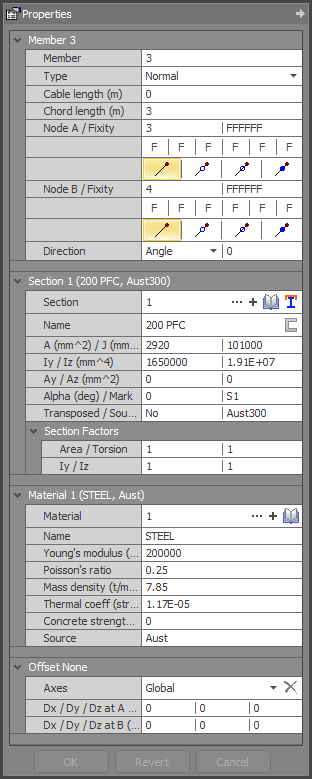
Member offset data
The member offset data is shown in the member properties data panel.
It is possible to specify a rigid member segment that doesn’t deform under bending at each end of a member. These rigid segments have infinite stiffness for bending, shear and axial deformations. Member offsets are very useful for modelling the very stiff area at the interconnection of members (especially stiff members such as large steel members or concrete members).

Member offsets
For example, the rectangular reinforced concrete frame shown above on the left could be modelled quite accurately with SPACE GASS using a model similar to the one shown on the right. Each member in the model has short member offsets at each end where intersecting members overlap.
Member offsets are also very useful in situations where the centrelines of connected members do not intersect at a node. For example, the diagonal brace members of a plane truss may intersect below the top chord centreline. Member offsets could be used to allow for this.
Member offsets could also be used to model the centreline mismatch when members of different depths are connected end-to-end with "top-of-steel" alignment.
Member offsets can be defined in global axes or in local member axes.
The "Convert member offset axes" tool lets you convert member offsets from global to local axes or vice-versa.
Member offsets are not just cosmetic because they also affect the analysis results, sometimes significantly. Offsets are equivalent to rigid elements that connect the ends of a member to its nodes, and these rigid elements can change the forces and moments in the member. For example, consider a beam that has opposing forces aligned with the beam applied at its end nodes. Under normal circumstances they would simply generate an axial force in the beam, however if the beam was offset upwards then moments could also be generated due to the applied forces being offset from the centroid of the beam.
![]() The
ends of a member with "local" offsets are offset relative to
an axis connecting the end nodes of the member rather than being relative
to the axis of the member in its final position.
The
ends of a member with "local" offsets are offset relative to
an axis connecting the end nodes of the member rather than being relative
to the axis of the member in its final position.
! IMPORTANT NOTE !
Be careful when sub-dividing members that have local offsets because the direction of the axis that the offsets are relative to will change when any intermediate nodes are added.
See also Member offset text.
See also Datasheet Input.
See also Member properties.
See also View node / member / plate properties.
See also Modelling member offsets.