Prescribed node displacements
This tool allows you to graphically specify displacements and rotations to nodes. The prescribed displacements are load case specific. Node displacements are always referenced to the global axes system and can only be applied to restrained degrees of freedom.
The procedure is as follows.
Select the nodes you wish to displace, click the right mouse button and then select "Loads" => "Prescribed Node Displacements" from the popup menu that appears.
OR
Select "Prescribed Node Displacements - Graphical" from the Loads menu, select the nodes you wish to displace, click the right mouse button and then click Ok.
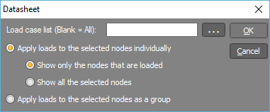
In the load case form that appears, if you are inputting new displacements then you would probably leave the load cases list field blank and specify the load cases in the datasheet that follows. If you are editing displacements then you may also wish to leave the load cases list field blank unless there are a large number of load cases and you want to restrict the datasheet to just some of them.
You should then choose between showing the displacements applied to each selected node individually (ie. one line of data for each node) or applied as a group to all the selected nodes (ie. one line of data for all the nodes). The advantage of the "group" selection is that you only have to input one line of data in the datasheet to have it applied to all the selected nodes. This can be particularly useful if you are applying the same displacement to a number of nodes. If you are inputting a different displacement on each node then you should choose the "individual" selection. Choosing "individual" can also be useful if you are simply trying to see what displacements are already applied to the nodes you have selected.
If you have elected to show the displacements applied to each node individually then you can also choose between showing all the selected nodes or just the ones that are displaced. If you are inputting new displacements then you would probably choose to show all the selected nodes, whereas if you are editing existing displacements or just viewing displacements then showing just the displaced nodes may be preferable.
A datasheet then appears with any existing displacements shown. You can add, edit or delete displacements and then click the Ok button to save any changes. The operation of the datasheet is the same as the non-graphical datasheets (see also Datasheets).
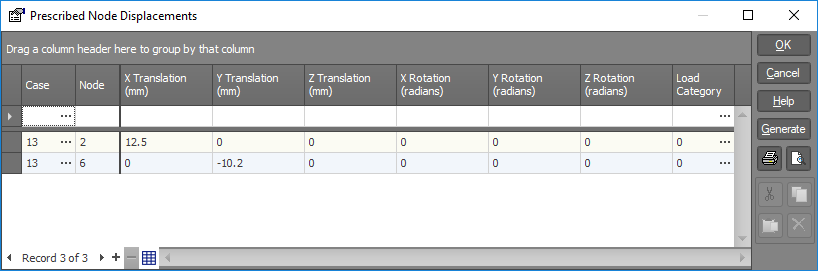
Refer to "Using datasheets" for information on how to operate the above datasheet.
See also Prescribed node displacement data.