Replace common nodes with constraint links
Plate elements are always rigidly connected to their nodes, and so if two panels modelled with plate elements are connected to each other, such as you could get with a slab connected to a wall, the connection along the slab-wall edge would also be rigid. In order to create a pinned or hinged connection along such an edge, each panel could have its own set of nodes and then the pairs of nodes along the edge could be linked with master-slave constraints. A constraint code of FFFRRR would achieve the desired result by forcing each pair of nodes to move together but rotate independently. Note that each pair of linked nodes can have the same coordinates so that they are directly on top of each other.
Similarly, a slab supported on a beam would by default have a rigid connection between the slab elements and the beam. If you didn't want any torsion to be transferred from the slab to the beam then master-slave constraints could also be used to link the slab nodes to the beam nodes.
If you have already created your model with a rigid connection between adjacent elements, it can be time consuming to separate the elements and then link them with master-slave constraints. However, the "Replace Common Nodes with Constraint Links" tool automates the whole process and makes this task easy.
In order to operate the tool with plate panels, you should select the plate elements in one panel, making sure that you select all the elements along the connecting edge and none of the elements in the other panel. You should then right-click, select "Plate Tools" => "Replace Common Nodes with Constraint Links" from the popup menu that appears, followed by selecting the plate elements in the other panel, again making sure that you select all the elements along the connecting edge. Note that during the second selection phase, the plate elements in the first selection are disabled for convenience and to ensure that they aren't selected twice.
The above procedure is similar if you are working with beam elements.
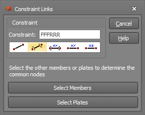
After clicking Ok, the following form appears, allowing you to set the constraint code. For a typical hinged edge connection you should leave it at FFFRRR so that each pair of nodes move together but rotate independently.
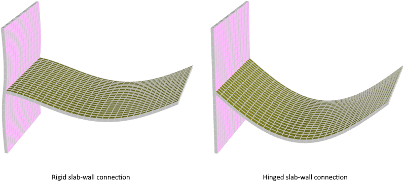
The following example shows a wall connected to a slab. The image on the left has them rigidly connected, while the image on the right has pairs of nodes along the intersecting edge with master-slave constraints of FFFRRR linking each pair of nodes.
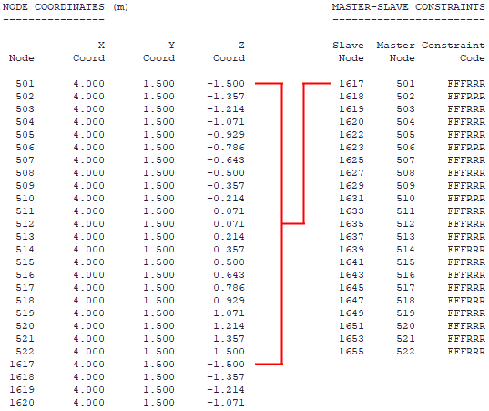
In the hinged model you can see from the data below that linked nodes (eg. nodes 501 and 1617) can have identical coordinates.