Master-slave constraint data
The master-slave constraint data is shown in the node properties data panel.
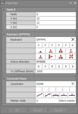
Master-slave constraints allow you to connect nodes together with imaginary links so that they translate and/or rotate together. The degree of constraint can be varied so that any or all of the six degrees of freedom of a node can be linked to another node. For example, it is possible to connect two nodes together with a 3D rigid link, a 2D rigid link, a 2D translational link, a 2D rotational link, a 1D translational link, a 1D rotational link or any other combination of the six degrees of freedom.
![]() A node which is linked to another node is termed a "slave node" and the node to which
it is linked is termed its "master node". A master node can have many slave nodes, however a slave node can have only one master node. A typical frame can have many slave nodes and many master nodes. A master node cannot be the slave of
another master node. A slave node constrained DOF cannot be a support (restraint).
A node which is linked to another node is termed a "slave node" and the node to which
it is linked is termed its "master node". A master node can have many slave nodes, however a slave node can have only one master node. A typical frame can have many slave nodes and many master nodes. A master node cannot be the slave of
another master node. A slave node constrained DOF cannot be a support (restraint).
A constraint link between a slave node and its master node not only affects the movements of the slave but also the master.
Node
Slave node to be constrained.
Master node
The node to which the slave node is to be constrained. You can select a master node by clicking the "Select" button and then choosing a node.
Constraint code
Master-slave constraints are controlled by a six character constraint code which specifies the exact constraint relationship between a slave node and its master. The six characters of the constraint code correspond to translational constraint along X, Y and Z and rotational constraint about X, Y and Z respectively. "F" represents fixed (constrained) and "R" represents released (unconstrained).
In order to illustrate how the constraint code works, we will consider some typical examples of constraints in the global XY plane. Please note that the following examples apply equally to the XZ and YZ planes also.
When considering the XY plane, the only significant characters in the constraint code are the first, second and sixth. These correspond to translation along X and Y, and rotation about Z. When considering the XZ plane, only the first, third and fifth characters apply, and when considering the YZ plane, only the second, third and fourth characters apply.
If a slave node has a constraint code of "RFxxxR" (where xxx could be any combination of F’s and R’s) then its Y-axis translation will be the same as its master node. Note that the X-axis translation and the Z-axis rotation of the slave node will be completely independent and in no way affected by its master node. This can be represented by the simple constraint equation Dys = Dym, where Dys is the slave Y-axis translation and Dym is the master Y-axis translation.
Similarly, if a slave node has a constraint code of "RRxxxF" then its Z-axis rotation will be the same as its master node and the X-axis and Y-axis translations will be independent. The constraint equation in this case is Rzs = Rzm, where Rzs is the slave Z-axis rotation and Rzm is the master Z-axis rotation.
A slightly different situation occurs if both a translational degree of freedom and a rotational degree of freedom are constrained. An example of this is a constraint code of "FFxxxF". In this case, the constraint code effectively places a 2D imaginary rigid member between the slave node and its master so that the translations of the slave node are a function of both the translations and the rotation of the master node. The constraint equations in this case are
Dxs = Dxm-Ly*Rzm
Dys = Dym+Lx*Rzm
Rzs = Rzm
where Lx and Ly are the horizontal and vertical components of the distance between the slave and master nodes.

Constraint movements
The following list shows some common constraint codes.
|
FRRRRR |
X translation constrained |
(Dxs=Dxm) |
|
RFRRRR |
Y translation constrained |
(Dys=Dym) |
|
RRFRRR |
Z translation constrained |
(Dzs=Dzm) |
|
RRRFRR |
X rotation constrained |
(Rxs=Rxm) |
|
RRRRFR |
Y rotation constrained |
(Rys=Rym) |
|
RRRRRF |
Z rotation constrained |
(Rzs=Rzm) |
|
FFFRRR |
X, Y and Z translations constrained |
(Dxs=Dxm) |
|
|
|
(Dys=Dym) |
|
|
|
(Dzs=Dzm) |
|
RRRFFF |
X, Y and Z rotations constrained |
(Rxs=Rxm) |
|
|
|
(Rys=Rym) |
|
|
|
(Rzs=Rzm) |
|
FFRRRF |
Rigid link in XY plane |
(Dxs=Dxm-Ly*Rzm) |
|
|
|
(Dys=Dym+Lx*Rzm) |
|
|
|
(Rzs=Rzm) |
|
FRFRFR |
Rigid link in XZ plane |
(Dzs=Dzm-Lx*Rym) |
|
|
|
(Dxs=Dxm+Lz*Rym) |
|
|
|
(Rys=Rym) |
|
RFFFRR |
Rigid link in YZ plane |
(Dys=Dym-Lz*Rxm) |
|
|
|
(Dzs=Dzm+Ly*Rxm) |
|
|
|
(Rxs=Rxm) |
|
FFFFFF |
Rigid link in all planes |
(Dxs=Dxm-Ly*Rzm+Lz*Rym) |
|
|
|
(Dys=Dym+Lx*Rzm-Lz*Rxm) |
|
|
|
(Dzs=Dzm-Lx*Rym+Ly*Rxm) |
|
|
|
(Rxs=Rxm) |
|
|
|
(Rys=Rym) |
|
|
|
(Rzs=Rzm) |
Any further combinations of the six character constraint code can also be specified.
The following diagrams show the effect that each of the XY plane constraints have. The effects shown apply equally to the XZ and YZ planes also. Note that constraint codes for any of the three planes can be combined together as can be seen in the examples above.

Typical constraint links
Master-slave constraints can be used to great advantage in many structures. They are particularly useful for modelling floor slabs in three dimensional frames. A typical floor slab may displace and rotate in plan as a unit but its plan dimensions do not change due to its large in-plane rigidity. This could be modelled in SPACE GASS by using one of the perimeter nodes in a typical floor slab as the master node for that floor and specifying all of the other perimeter nodes in that floor to be slaves of the master node in the in-plane (XZ plane) directions using a constraint code of "FRFRFR". Thus all nodes in the floor would move as a unit in the in-plane (horizontal plane in this case) directions. They would still, however be free to move independently in the out-of-plane (vertical) direction.

Rigid diaphragm modelled with constraints
Another example is the case of wind bracing or a scissor lift where two continuous members cross each other and are connected to each other with a bolt or pin. The pin transfers shear from one member to the other but not moment so that the members are free to rotate about the pin independently.

Scissor lift modelled with constraints
This situation is very difficult to model in a frame analysis program unless a constraint facility is available. Using a master-slave constraint, it is a simple matter to locate two nodes on the same point where the two members cross. One of the members would be connected to the first node and the other member would be connected to the second node. Assuming that the frame was in the XY plane, a constraint code of "FFRRRR" could then be used to force the two nodes to translate together but rotate independently.
A third example of a common master-slave constraints application is in the modelling of a shear wall. A column of nodes consisting of one master and the rest slaves could be used to form the wall itself. Any other nodes connected directly to the wall could also be slaves of the master. Assuming that the wall was in the XY plane, a constraint code of "FFRRRF" could be used.
Another situation which is difficult to model without using a master-slave constraint occurs when two members of different depths are connected together end-to-end such that their centrelines do not line up. In such cases a node could be placed at the end of each member and then a master-slave constraint could be used to join the two nodes together with a rigid link.
In some situations, short stiff members could be used as an alternative to constraint links, however they would be susceptible to ill-conditioning problems, particularly if they were very stiff in comparison to other members in the structure.
![]() Master-slave constraints do not suffer from ill-conditioning problems, regardless of how short
the links are.
Master-slave constraints do not suffer from ill-conditioning problems, regardless of how short
the links are.
![]() The accuracy of a dynamic frequency analysis depends on correct placement of the master nodes.
Each master node must be placed as close as possible to the centre of mass of its slave nodes. If this is not done then the rotational inertia of the mass distributed to master nodes may not be accurate and this could affect the results of the dynamic
frequency analysis. Note that this only affects dynamic frequency analysis and is not a requirement for static analysis.
The accuracy of a dynamic frequency analysis depends on correct placement of the master nodes.
Each master node must be placed as close as possible to the centre of mass of its slave nodes. If this is not done then the rotational inertia of the mass distributed to master nodes may not be accurate and this could affect the results of the dynamic
frequency analysis. Note that this only affects dynamic frequency analysis and is not a requirement for static analysis.
![]() Master-slave constraints can be used to model a hinged connection between a wall and slab that
have been modelled with plate elements. For more information refer to "Replace edge connections with constraint links".
Master-slave constraints can be used to model a hinged connection between a wall and slab that
have been modelled with plate elements. For more information refer to "Replace edge connections with constraint links".
See also Master-slave constraints text.
See also Datasheet Input.
See also Node properties.
See also View node / member / plate properties.