Moving loads
The moving loads tool generates a series of load cases that represent the effect of loads moving along a structure. Common applications include moving or stationary vehicles on a bridge, a crane travelling along a crane rail in a building or material moving along a conveyor. Each load case represents a point in time, and the loads generated from the moving wheels or pressure patches for that load case are distributed onto the closest members or plates.
- Loads can be moving or stationary.
- Load sources can be wheeled vehicles such as trucks or cranes, or distributed loads such as pressure patches or line loads.
- Multiple scenarios allow you to model any combinations of moving and stationary loads.
- Moving loads can be combined with other static loads.
- A lane generation tool is included for roads and bridges.
- Travel paths and lanes can have multiple segments, including curved segments.
- Loads can be generated on nodes, members and plates.
- Libraries of standard vehicles are included for various countries.
- Custom vehicles and libraries can be created.
- Loads can share common travel paths or lanes.
- A speed, delay and start position can be specified for each load.
- Load factors, lane factors and dynamic load allowances can be specified.
- A loading area can be defined so that loads which move outside of it become inactive.
- A vertical proximity setting enables independent generation of loads on multi-level roadways or bridges.
- Moving load data can be exported to MS-Excel, MS-Word or a text file.
- Moving load data can be imported from MS-Excel or a text file.
- An animated display allows you to view your loads moving along the structure.
Overview
The moving loads tool lets you define sets (scenarios) of moving loads (vehicles, cranes, pressure patches, line loads, etc) that move along your model. As the loads move, SPACE GASS takes a snapshot of their position at a regular time interval and creates a load case for each point in time. If you view the load cases one after another it gives the appearance of the loads moving along the model. Once the moving load cases have been generated you can combine them with other load cases, analyse them or perform design checks on them.
In order to proceed, you must first create a moving load scenario that defines a set of load cases to be generated. The scenario has a name, a starting load case number and a time interval that represents the time between load cases. Often only one scenario is required, however you can create multiple scenarios if you wish to examine different situations such as various combinations of vehicles moving along a bridge.
You can then add vehicles and/or pressures to the scenario, each of which contains a name, type, magnitude, travel path, load factors, start position, speed and delay. A vehicle consists of a set of wheels (with their positions and loads) and can be defined directly or imported from a standard library. A pressure consists of a width, length, pressure magnitude (in three directions) and load spacing. Each scenario can contain multiple vehicles and pressures, each moving at different speeds, with different magnitudes, starting positions, delays and in different directions if required. The load's speed multiplied by the scenario's time interval defines the distance travelled by the load from one load case to the next.
Stationary loads can be modelled by just specifying a zero speed. Pressure loads with a zero length are also treated as stationary and are applied to the entire travel path length. Stationary loads can be put into just the starting load case or added to each load case that contains moving loads.
A travel path, which determines where the vehicle or pressure travels, can have multiple straight or curved segments that can go in any direction or around corners. If multiple loads use the same travel path then it only needs to be created once and can then be shared between all the loads that reference it. Travel paths can be defined graphically or via a data table, plus a travel path generation tool lets you set up your bridge lanes or parallel travel paths quickly in one operation.
Finally, you must select the members and/or plates that could be directly loaded by the moving vehicles or pressures. Loads are only applied to the members or plates you have selected, and so for bridges it is normal to select only the members and/or plates in your bridge deck, or for cranes it is normal to select only the beams that the crane wheels are in direct contact with.
When the moving loads tool generates the load cases for a scenario, it calculates the position of each vehicle or pressure along its travel path at each point in time and then distributes its loads onto the closest members or plates that support it. Each component of a vehicle or pressure is active if it is within the ends of the load's travel path and within the loading area that you can specify. If you have ticked the vertical proximity distance option then only the members or plates that are within that distance vertically from the vehicle or pressure will be loaded.
At any time after creating a scenario, you can produce an animated view of the vehicles and pressures moving along your model. After the loads have been generated, you can use the keyboard PageUp/Dn keys to scroll through the load cases and effectively see the loads moving across your model.
Operating procedure
The following steps assume that your job doesn't yet contain any moving load data. If moving load data already exists then you can simply skip the steps for which data already exists.
The order of the steps given below is a logical sequence that should work well for most jobs, however other than having to create at least one scenario first, the order is not important and can be changed to suit your desired workflow.
Step 1 - Getting Started
You can begin by either:
-
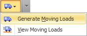
Clicking the "Generate Moving Loads" button in the top toolbar without first selecting any members or plates.
This is the recommended most method for most applications. You can set up your travel paths and select the members and plates to be loaded later.
-
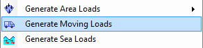
Selecting the members or plates that will be in direct contact with the moving loads, right-clicking and then selecting "Loads" => "Generate Moving Loads" from the popup menu that appears.
This method is recommended if the loads move along a single line of members such as along a crane rail in a building. If the members you select form a single line of members connected end-to-end then the moving loads tool will automatically set up an initial travel path along this line of members, plus it will treat the members you selected as the ones to be loaded. Of course you can change the travel path and the loaded members from inside the moving loads tool at any stage.
Regardless of which of the above methods you use to start the process, the selection of the members and plates to be loaded will be remembered by the module and so you don't have to re-select them each time you open the moving loads tool.
Step 2 - Creating a Scenario
If no moving load data exists for the job then the "Scenario Properties" form will open automatically, allowing you to create your first scenario. If moving load data already exists then you will be taken to the main moving loads form instead, and you can create a scenario by clicking the "Add Scenario" button.

Each scenario represents a particular configuration of loads moving along your structure. A scenario may contain a number of vehicles, pressure patches or line loads, either stationary or moving at different speeds with different starting positions, delays and in different directions. In many cases you will only need one scenario, however if you are modelling something like a multi-lane bridge then you may need a different scenario for each combination of vehicles in the various lanes.
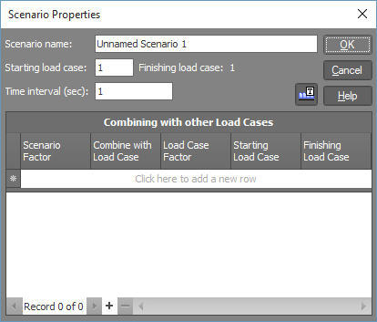
When creating a scenario you must specify a scenario name, a starting load case and a time interval. The name is simply used to identify the scenario and can be any descriptive text. The starting load case is the first in the set of consecutive load cases that will be generated for the scenario, and the time interval is the interval between load cases for the scenario. The finishing load case is calculated automatically for each load and depends on a number of parameters as follows:
Finish = Start + (TPLen + LLen - SPos) / (Speed x Interval) + Delay / Interval,
where Start is the scenario's starting load case, TPLen is the length of the load's travel path, LLen is the length of the load (eg. 25m for an Australian M1600-6.25 vehicle), SPos is the load's start position along the travel path, Speed is the load's speed, Delay is the load's starting delay and Interval is the scenario's time interval.
The overall finishing load case for the scenario is the maximum of the finishing load cases for all of the loads in the scenario.
You can also combine the moving load cases with other static load cases by filling out the table at the bottom of the scenario properties form. For more information refer to "Combining scenarios with other static load cases" below.
Step 3 - Adding Loads
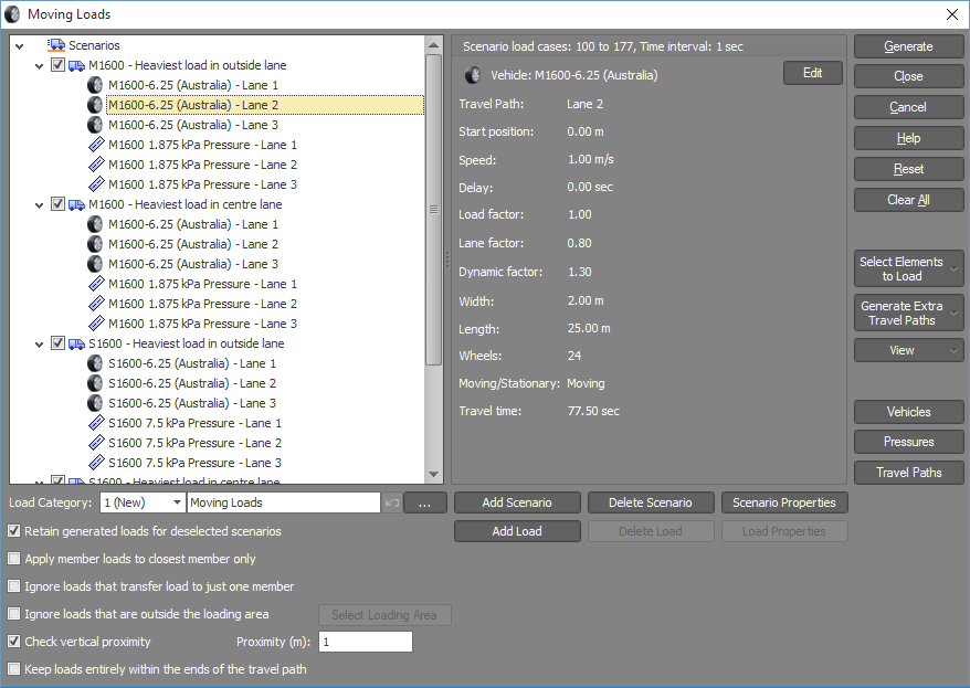
Once the first scenario has been created, the main moving loads form appears as follows. You are now ready to add loads to the scenario.
![]()
Adding loads is simply a matter of clicking the "Add Load" button and then inputting data into the following form.
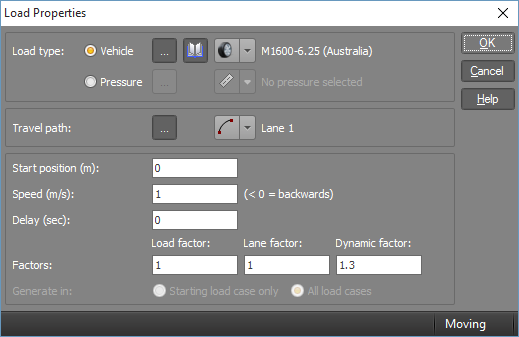
For each load you must specify its type as a vehicle or a pressure, select a travel path, and then specify a start position, speed, delay and load factors.
Normally the front of a moving load will start at the beginning of the travel path at time zero and continue until the rear of the vehicle reaches the end of the travel path. Alternatively, you can start your load part-way along the travel path by specifying a non-zero start position and/or you can change its start time by giving it a delay. Delays are very useful if you wish to model vehicles that follow each other on a bridge for example.
The speed setting controls the distance each load travels over the scenario's time interval. This distance is also the change in position of the load between successive load cases for the scenario. If you wish to model a reversing vehicle then just specify a negative speed. Note that a reversing vehicle will still move in the same direction along the travel path as a forward moving vehicle.
Stationary loads can be modelled by simply giving them a zero speed. Note that the start position and delay settings are still active for stationary loads.
If you have a stationary pressure or line load that extends along the entire travel path length, you can model this by specifying a zero pressure length. In this case the speed and start position settings will be ignored.
The load factor, lane factor and dynamic factor allow you to factor your loads up or down to satisfy the design code requirements. For example, the lane factor usually depends on how many lanes are loaded and, for 3 lanes or more loaded, it is typically 1.0 for the first lane, 0.8 for the second lane and 0.4 for the other lanes. The dynamic factor is equal to (1 + a), where a is the dynamic load allowance that depends on the type of vehicle being used. All three factors are multiplied together to give an overall load factor and so if a particular factor is not applicable to your situation, such as if you are modelling a crane travelling in a building and so there is no lane factor, you should just set the irrelevant factor(s) to 1.0.
The "Generate in" field is enabled for stationary loads and controls whether the load is placed just into the starting load case or into every load case. If you specify "Starting load case only" then the stationary loads will go into the starting load case and the moving loads will begin in the next load case. If you specify "All load cases" then the stationary and moving loads will be combined and will begin in the starting load case.
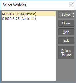
For a vehicle you can select from a list of vehicles that are already being used in the job, select a vehicle from a library, create a new one or edit an existing vehicle by clicking the following buttons in the "Load Properties" form.
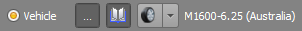
 Click this button to select from a list of vehicles that are already in use in the job. Selecting an existing vehicle will allow it to be shared
between multiple loads. If there are currently no vehicles in the job then this button will be disabled.
Click this button to select from a list of vehicles that are already in use in the job. Selecting an existing vehicle will allow it to be shared
between multiple loads. If there are currently no vehicles in the job then this button will be disabled.
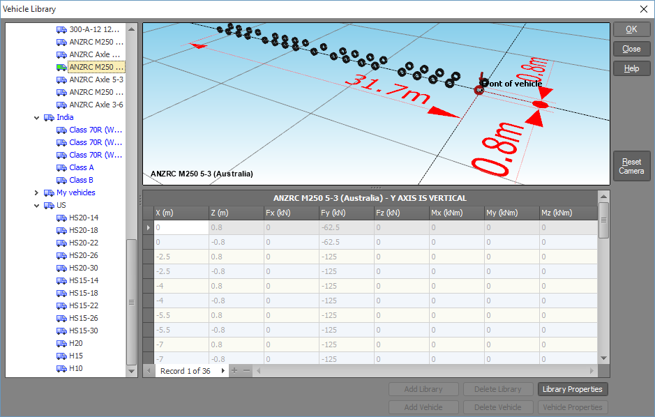
 Click this button to select a vehicle from one of the libraries supplied with SPACE GASS or from a custom vehicle library you created previously.
 Click this button to create a new vehicle or edit an existing one.
When editing a vehicle or creating a new one, you must specify a name, together with each wheel's position relative to the front of the vehicle and the forces and moments that the wheel exerts on the structure.
For a pressure you can select from a list of pressures that are already being used in the job, create a new one or edit an existing pressure by clicking the following buttons in the "Load Properties" form.
Click this button to select from a list of pressures that are already in use in the job. Selecting an existing pressure will allow it to be shared
between multiple loads. If there are currently no pressures in the job then this button will be disabled.
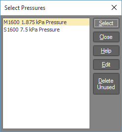
 Click this button to create a new pressure or edit an existing one.
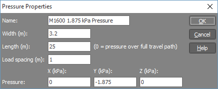
When editing a pressure or creating a new one, you must specify a name, together with the width, length, load spacing and magnitude of the pressure. When a pressure is distributed onto the members or plates in your structure it is approximated by a grid of uniformly distributed point loads spaced at the "Load spacing" setting that you specify. If you use a small load spacing then you will get a more accurate load distribution than you would with a large load spacing, however a smaller load spacing will also result in many more loads being generated.
If you wish to generate a line load then you should simply specify a pressure width that is less than the load spacing. For example, in order to generate a 6kN/m line load with a load spacing of 0.5m you could specify a width of 0.1m and a pressure of 60kPa. Alternatively, a width of 0.25m with a pressure of 24kPa would give exactly the same result.
If you have a stationary pressure or line load that extends along the entire travel path length, you can easily model this by specifying a zero pressure length. In this case the speed and start position settings will be ignored.
Step 4 - Defining Travel Paths
Each load in a scenario must be associated with a travel path so that SPACE GASS knows where the load is going. Even stationary loads need a travel path in order to identify their position and orientation.
If you are modelling a multi-lane bridge then you should think of each lane as a travel path. Once you have defined the travel path for your first lane you can use the lane generation tool (explained below) to generate the other lanes simply by specifying the lane width and the number of lanes required. In fact, it is often a good idea to skip "Step 3 - Adding Loads" above, set up all your lanes first and then go back to step 3 to add your loads.
You can add a travel path or select an existing one by clicking the following buttons in the "Load Properties" form.
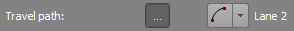
Click this button to select from a list of travel paths that are already in use in the job. Selecting an existing travel path will allow it to
be shared between multiple loads. If there are currently no travel paths in the job then this button will be disabled.
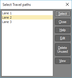
When selecting a travel path from the above list, if you are unsure of which travel path is which, you can click the "View" button to show them all graphically.
 Click this button to create a new travel path or edit an existing one.
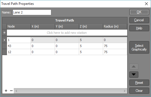
A travel path consists of a sequence of straight line or curved segments. Each travel path station is defined by a node number and/or X,Y,Z coordinate. If a station is defined by a node number and a coordinate then the coordinate is added to the node position. For example, in the table below, the travel path is parallel to a line joining nodes 1, 43 and 12 and offset 5m in the global Z direction from that line. If you wish to define a travel path station using just coordinates then the node number should be zero for that station.
Curved segments can be defined by a non-zero radius at the end of the segment. The travel path below has two segments, each with a radius of 75m. Any radius specified for the first station of the travel path (ie. in the first line of the table) is ignored.
If you don't wish to type the travel path stations directly into the table, you can click the "Select Graphically" button and then select the stations graphically by clicking on nodes, members or points off the structure.
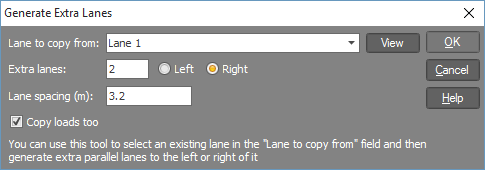
If you are modelling a multi-lane bridge then once you have defined the travel path for the first lane, you can use the "Generate Extra Travel Paths" => "Generate Lanes" button in the main moving loads form to generate the other lanes.
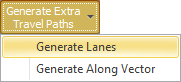
It is just a matter of selecting the first lane in the "Lane to copy from" field, specifying how many extra lanes to generate and the lane spacing. The extra lanes can be generated to the left or right of the first lane. If you're not sure which lane to select in the "Lane to copy from" field then you can click the "View" button next to it to view the existing travel paths graphically before proceeding with the generation. Any curved segments will have their radius increased or decreased in the generated lanes so that the center of curvature of all lanes is maintained.
Note that bridge lanes are no different to other travel paths. The only reason they have their own generation form is to make it easier for the user by tailoring the generation input data to lane specific items.
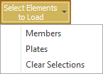
You can also generate extra travel paths by clicking the "Generate Extra Lanes" => "Generate Along Vector" button.
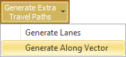
It is similar to the lane generation form above except that the lane spacing field is replaced by a copy vector. Travel paths generated this way will be identical to the original travel path and spaced apart as defined by the copy vector. The radius in curved segments will not be adjusted in the generated copies.
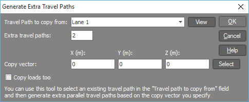
Step 5 - Selecting the Members and Plates to be Loaded
Before the moving and stationary loads can be generated, you must specify which members and/or plates in your model that the vehicle wheel loads and pressures are distributed onto. After choosing "Members" or "Plates" from the following menu you should select them graphically either by clicking them directly or via selection windows in the normal way. If your model contains both members and plates that could be loaded then you should select both the members and the plates. Note that you can't select members and plates at the same time and so if you need to select both members and plates then you should select the members first followed by the plates (or vice-versa).
It is important that you select all the members and plates that could be directly loaded by the vehicle wheels or pressures because any that are not selected won't be loaded even if a wheel or pressure passes directly over them. Conversely, if you select members or plates that aren't directly loaded (such as sub-structure members below a bridge deck) then they may take loads incorrectly that are supposed to be applied to other members or plates higher up.
Once you have made the member and/or plate selections they will be remembered and saved with the rest of the moving load data. This means that you don't have to re-select them each time you open the moving loads tool.
If you selected some members or plates and then opened the moving loads tool via the right-click menu (ie. using method (b) in "Step 1 - Getting Started" above) then those members or plates will already be selected and you don't have to re-select them here. You can, however, use the "Select Elements to Load" button to edit your selection if required.
Step 6 - Finalizing Your Moving Load Data
As you create scenarios, add loads and define travel paths, they will appear in the tree on the left side of the main moving loads form as shown below. You can edit any of your data by clicking the "Add", "Delete" or "Properties" buttons at the bottom, or by clicking the "Edit" button near the top of the right-hand side panel.
Better still, you can edit any of your data by just double-clicking the desired item in the tree on the left.
In order to visually check the loads and travel paths, you can click the "View" button and then select between loads and travel paths.
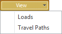
Followed by ticking the scenarios or travel paths you wish to view in the following form.
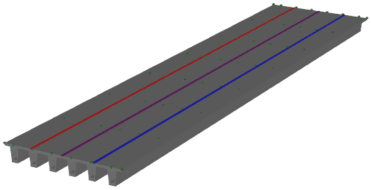
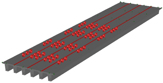
If you select loads then when you click Ok they are shown moving across your model as follows:
Or if you select travel paths then when you click Ok they are shown as follows:
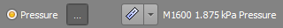
Before generating the moving loads, you need to set the following options correctly.
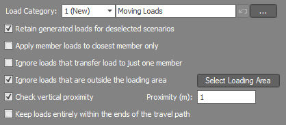
The "Load category" field lets you specify which load category the generated loads will go into. For more information refer to "Load categories".
If you have multiple scenarios with one or more of them deselected (ie. unticked in the scenario tree) then, provided that the "Retain generated loads for deselected scenarios" option is ticked, the loads that were previously generated for the deselected scenarios will be retained. If you want the loads for the deselected scenarios to be cleared then you should untick this option.
Normally, loads that don't fall directly on a member are distributed to the closest surrounding members in proportion to their distance from the load, however if the "Apply wheel loads to closest member only" option is selected then each load will be applied only to the member that is closest to it. This reduces the number of loads that are generated while still providing sufficient accuracy in most cases.
Each vehicle or pressure is active while it is between normals that extend from the two ends of its travel path. It is possible, however, that you may want wheels or parts of a pressure area to become inactive at certain times even though they are still within the extents of the travel path. For example, if a wheel moves off the side of a bridge or moves off the end of a skew bridge, you may want it to become inactive before it reaches the end of its travel path. You can achieve this by clicking the "Ignore loads that transfer load to just one member" option. This has the effect of ignoring wheels or parts of a pressure area that would have their load distributed to just one member unless the load is directly on that one member. It solves the problem of deactivating loads that move off the structure in most cases.
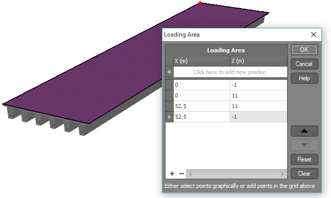
For situations in which the above option is not suitable, you can specify a polygon that defines a loading area. Wheels or parts of a pressure area that fall outside of the loading area are treated as inactive. You can define the loading area graphically by clicking the "Select Loading Area" button in the main moving loads form and then selecting points around your model that represent the limits of the loading area.
When loads are distributed onto the surrounding members or plates, their vertical position is usually ignored. The problem with this is that if you have a multi-level bridge for example, any vehicles that are on an upper bridge deck could also have their load incorrectly applied to a lower deck if it is vertically below the vehicle. The "Check vertical proximity" setting solves this problem by only distributing load to the members or plates that are positioned vertically within the "Proximity" distance of the load.
The "Keep loads entirely within the ends of the travel path" option is intended for loads that can't move beyond the ends of their travel path. It is useful for applications such as travelling overhead cranes that can only move within the ends of the crane rail. If ticked then loads begin with their rear at the start of the travel path (plus any offset that might be applied) and finish when their front reaches the end of the travel path. If this causes loads to be temporarily stationary, such as if they have a start delay or if they reach the end of the travel path while other loads in the scenario are still moving, they will apply load to the structure in their stationary position. This option also causes all loads that share a travel path within a scenario to stop moving as soon as one of them reaches the end of the travel path.
The "Keep loads entirely within the ends of the travel path" option should be unticked for situations such as material moving along a conveyor or road traffic on a bridge in which the loads approach the start of the travel path, move along it and then disappear off the end.
Step 7 - Generating the Moving Loads
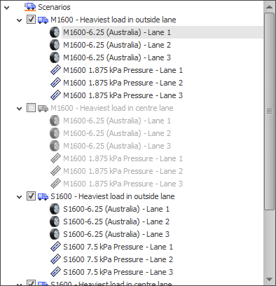
Once you have created all the required scenarios, loads and travel paths, you should click the Generate button to initiate the load generation.
If you don't want to generate data for every scenario then you can disable some of them by deselecting (unticking) them in the tree on the left. In the following example the "M1600 - Heaviest load in centre lane" has been deselected and so it is temporarily disabled and no loads will be generated for it when you click the "Generate" button. Note that any loads that were previously generated for the deselected scenarios will be retained if the "Retain generated loads for deselected scenarios" option is ticked. If this option is unticked then all previously generated loads for the deselected scenarios will be deleted.
During the generation, each wheel of a vehicle is treated as a load source that has its load distributed onto the structure. Pressure loads are approximated by a grid of equally spaced point loads that are also distributed onto the structure. For each wheel load or pressure point load, if it falls on a plate then it is distributed to the plate's corner nodes in proportion to their distance from the load. If it doesn't fall on a plate then it is distributed to the surrounding members in proportion to their distance from the load or onto a single member if it falls directly on that member or if the "Apply member loads to closest member only" option is ticked.
Once the load generation has finished, you can use the keyboard PageUp/Dn keys to scroll through the load cases and see effect of the generated loads moving across your structure.
All primary and combination load cases generated with the moving loads tool are given load case titles that reflect their properties. Each title includes a heading and a notes field. Please ensure that you don’t edit or delete the notes field as it is the means by which the program keeps track of which load cases belong to which scenario.
Envelopes
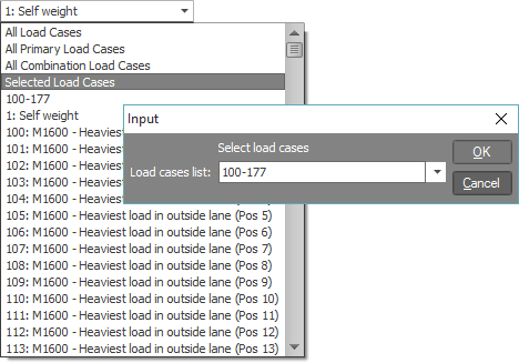
After the job has been analysed, you can display bending moment or shear force envelopes by clicking the "Selected Load Cases" item in the load cases combo box in the top toolbar and then typing in the range of load cases that have just been generated for a scenario. For example, if load cases 1 to 35 were generated, you should type 1-35 into the load cases field. Note that this may not always be necessary as the load cases field is automatically set by SPACE GASS for the first scenario whenever moving loads are generated.
On the side toolbar, you should then ensure that the envelope button  is depressed and the desired bending moment
  or shear force
  diagram button is depressed.
Combining scenarios with other static load cases
The load cases generated for a scenario can be combined with other static load cases using the table at the bottom of the scenario properties form. This is necessary when the moving loads need to be combined with other load cases such as dead loads, live loads, etc.
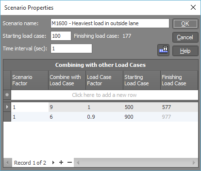
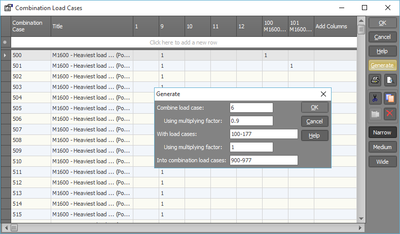
For example, in the above form, the scenario 1 moving loads will be combined with static load case 9 to form a set of combination load cases starting at load case 500. A further set of combination load cases starting at 900 will combine the scenario 1 load cases with static load case 6 factored by 0.9.
You can see this has the potential to generate a huge number of load cases and you may, therefore, need to increase the "Maximum load cases" value via the "Problem size limits" item of the Settings menu.
If you need to combine a scenario with more than one static primary or combination load case, simply create a combination load case that combines the primary and combination load cases into a new combination load case first and then combine the scenario with that new combination load case. Remember that combination load cases can be combined into further combinations up to four levels deep.
Combining scenarios with other load cases increases the risk of overwriting existing load cases and having load case clashes due to overlapping of load cases between scenarios and combinations. SPACE GASS checks for these occurrences and prevents the load generation from proceeding if any problems are detected.
If you don't want to use the "Combining with other Load Cases" table in the scenario properties form above then you can also combine sets of load cases using the "Generate" button in the normal combination load cases datasheet. This has the added advantage that you can change your combinations at any time without having to re-run the moving load generation. The following example would combine load case 6 factored by 0.9 with load cases 100-177 factored by 1.0 into combination load cases 900-977. It would achieve exactly the same thing as the second line in the "Combining with other Load Cases" table above.