Plate cut data
Plate cuts are used to obtain the forces and moments in cross sections that can be drawn as "plate cuts" anywhere across the surface of a panel such as a slab or wall that has been modelled with plate elements.
The algorithm for calculating plate cut results has been improved in SPACE GASS 14.10 so that the results are accurate even if plate cuts are located close to points of stress concentration such as you would get with an internal corner of a panel.
The components of a plate cut are explained below. For information on creating and editing plate cuts refer to "Plate cuts".
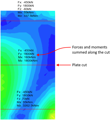
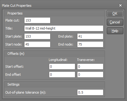
Plate cut
This is used to identify the plate cut and can be set to any number. It is set by default to match the start plate number for easy identification.
Title
The title can be used to describe and identify the plate cut.
Start plate
The plane of the plate cut is set to match the plane of the start plate. When drawing a new cut, you can set the start plate by hovering over it until it highlights and then drawing from one of its nodes. If you draw a plate cut from a node that is connected to plates that lie in different planes (eg. from the corner or edge of a box structure) then it is important that you select the correct start plate, otherwise your cut may finish up in the wrong plane.
End plate
This is the plate connected to the end of the cut.
Start and end node
These are the nodes that the plate cut is connected to. They must be connected to the start and end plates.
Offsets
Longitudinal offsets are used to shorten or lengthen the cut at either end, whereas transverse offsets are used to move the cut sideways. A positive transverse offset will move the cut to the left when looking from the start of the cut towards the end.
Out-of-plane tolerance
The plate cut forces and moments are calculated based on the values from the underlying plate elements that fall within the length of the cut on either side of it. The out-of-plane tolerance allows you to eliminate any contribution from plate elements that are too far away in the out-of-plane direction from the plane of the cut. For example, if you have defined a plate cut for a particular shear wall in a building, the out-of-plane tolerance eliminates any contribution from the plate elements in a shear wall behind or in front of the wall with the cut. Note that the out-of-plane tolerance is measured to a plate element's nodes and ignores any offset that the plate element might have.
The "Out-of-plane" tolerance setting is very important to get right if you have a plate cut on a surface that isn't completely flat.
Sign conventions
The sign conventions of the plate cut forces and moments are related to the local axes of the plate cut. The key sign conventions are as follows:
A positive Fy indicates compression along the local y-axis at the cut.
A positive Mx indicates bending about the x-axis causing compression on the positive local z-axis side of the cut.
A positive Mz indicates bending about the z-axis causing compression on the positive local x-axis side of the cut.
Plate cut results
Plate cut results are calculated from the plates on the positive local y-axis side of the cut. This means that if you reverse the direction of the plate cut then the direction of the local y-axis will be reversed and consequently the results will be taken from the plates on the other side of the cut, which may in some cases yield different results. For example, if plates are only present on one side of a cut then you will get results from those plates if the cut's local y-axis points towards them, however if the local y-axis points towards the side that has no plates then the results will be zero!
For a more complete discussion about plate cut results and some important factors to be aware of, refer to "Plate cuts".