Spectral load data
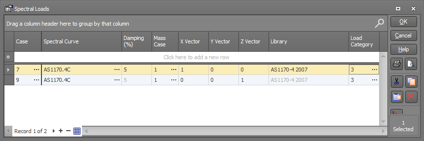
In order to perform a spectral response (earthquake) analysis, you must first create one or more spectral load cases. A spectral load case contains a list of modes, a spectral curve (and its associated damping factor), a mass load case and a direction vector. Spectral load cases can be combined, and multiple spectral load cases can be analysed simultaneously.
![]() A dynamic frequency analysis must have been performed before the spectral response analysis
can proceed.
A dynamic frequency analysis must have been performed before the spectral response analysis
can proceed.
Case
The spectral load case being created (see also "load cases" below).
Spectral curve
The name of the spectral curve (or "response spectrum") to be used with each spectral load case. You can input or change the spectral curve by clicking the  button (circled in red) in the spectral curve cell or by clicking the
  button. If you wish to change the spectral curve for multiple spectral
load cases at once then you should select them and then click the button.
button. If you wish to change the spectral curve for multiple spectral
load cases at once then you should select them and then click the button.
Under normal circumstances you should use the normalized response spectra provided with SPACE GASS for the particular loading code being used (ie. choose from the "AS1170.4", "NZS1170.5" or "IS1893" spectra in the spectral curve library), however you can also choose non-standard spectral curves from the library if required. The normalized response spectra are defined in AS1170.4-2007 section 6.4, NZS1170.5-2004 section 3.1.2 or IS1893.1-2016 section 6.4.2.
The response spectra in IS1893.4-2015 are slightly different to those in IS1893.1-2016 in that they extend to 10 seconds (refer to IS1893.4-2015 Annex B) instead of staying constant after 6 seconds (refer to IS1893.1-2016 6.4.2). If IS1893.4-2015 is selected as the loading code then the response spectra as per Annex B are used internally.
Damping
The damping factor associated with the nominated spectral curve. This value is built into each spectral curve when it was derived and cannot be changed. It is included in the datasheet for display purposes only.
Mass case
The mass load case for which the specified mode shapes have been (or will be) calculated from a dynamic frequency analysis.
Direction vector
Defines the direction of the ground vibration. For example, an earthquake acting in the X direction would have a direction vector of 1,0,0 (ie. Dx=1, Dy=0 and Dz=0). Note that the magnitude of the vector is unimportant and so direction vectors of 1,0,0 and 2.5,0,0 would have an identical effect.
Most loading codes require you to consider earthquake forces in the two orthogonal horizontal building directions, plus combinations comprising 100% of the forces in one direction combined with 30% of the forces in the other. You could model this by defining two spectral load cases with direction vectors of 1,0,0 and 0,0,1 (if Y is vertical) or 1,0,0 and 0,1,0 (if Z is vertical) and then various combination load cases that combine them in the 100% and 30% proportions.
If you need to analyse the effect of vertical shaking then you should also define a spectral load case with a vertical direction vector. Spectral load cases with a vertical direction vector are analysed with a reduced acceleration in accordance with AS1170.4-2007 7.2(3), NZS1170.5-2004 3.2 and IS1893.1-2016 6.4.6. No base shear scaling is done when the direction vector is vertical.
Load category
The load category column lets you specify which load categories the loads will go into. For more information refer to "Load categories".
Load cases
As discussed in "Direction vector" above, it is common practice to define two spectral load cases per mass load case (one for each of the orthogonal horizontal directions), plus various combinations of them. The Australian, New Zealand and Indian code-specific requirements for the combinations are given in AS1170.4-2007 5.4.2.1, NZS1170.5-2004 5.3.1 and IS1893.1-2016 6.3.2.2. Furthermore, because the dynamic vibrations oscillate from one side to the other, it is also necessary to consider the reverse of all the primary and combination load cases.
For example, consider two basic spectral load cases defined for a particular mass load case as follows:
Load case 21 = Direction vector 1,0,0 (ie. earthquake in X-axis direction)
Load case 22 = Direction vector 0,0,1 (ie. earthquake in Z-axis direction)
If the loading code requires further combinations of the above load cases in the form of 100% of the actions in one direction plus 30% of the actions in the perpendicular direction then further load cases are required. These are most conveniently input as combination load cases as follows:
Load case 23 = 1.0 x Load case 21 + 0.3 x Load case 22
Load case 24 = 1.0 x Load case 21 - 0.3 x Load case 22
Load case 25 = 1.0 x Load case 22 + 0.3 x Load case 21
Load case 26 = 1.0 x Load case 22 - 0.3 x Load case 21
Finally, the reverse of the all the above load cases must be defined as further combination load cases as follows:
Load case 31 = -1.0 x Load case 21
Load case 32 = -1.0 x Load case 22
Load case 33 = -1.0 x Load case 23
Load case 34 = -1.0 x Load case 24
Load case 35 = -1.0 x Load case 25
Load case 36 = -1.0 x Load case 26
Thus, each pair of basic spectral load cases can spawn up to a further ten combination load cases.
If you need to take into account the extra torsion due to accidental eccentricity of the horizontal earthquake actions as required by many of the seismic loading codes then further spectral and combination load cases are also required. For more details refer to "Accidental eccentricity".
If you want to combine the spectral analysis results with static analysis results then you should create further combination load cases that combine the static and spectral load cases and combinations.
The structure should be designed to resist the envelope of all of these load cases.