Creating and editing concrete beams
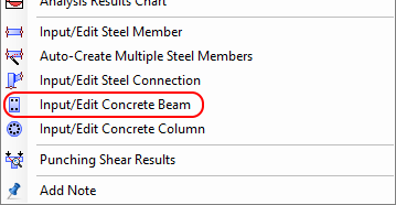
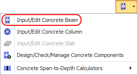
In order to define a concrete beam, it is simply a matter of selecting the members that make up the beam, clicking the right mouse button and then selecting "Input/Edit Concrete Beam" from the menu that appears or by clicking the  button in the top toolbar and then selecting "Input/Edit Concrete Beam".
Note that the reinforced concrete beam module does not let you input the cross section shape or dimensions. The cross section geometry is taken from the beam's section properties and must have been defined earlier by you using the shape builder.
The beam is then designed and the results are presented in the concrete beam editor shown below.
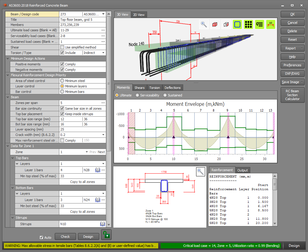
From there, you can examine the beam, click the Ok button to save and exit if you happy with it, or make changes to customize it to your exact requirements.
Before accepting the design results, you must ensure that the beam's supports have been correctly detected! See "Support detection" below for further information.
The status bar
The status bar at the bottom of the editor indicates whether the beam has passed, failed or passed with a warning. It includes the critical load case, the critical zone, the utilization ratio and a brief explanation of the failure mode or warning message. A green line indicates it has passed, red indicates failure and yellow is for a pass with a warning message. All of these colors can be changed via the "Preferences" button.


Blue may also be used in some circumstances to display other types of messages.

Data panel
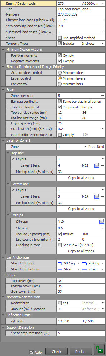
The data panel on the left of the concrete beam editor lets you make changes to the design data which are then reflected in the diagrams and tables in the editor. More information about specific items in the data panel is presented in the following sections below.
Checking and Designing
When you first create a beam and open it in the editor it does an initial design and then displays "Design" at the end of the status bar. If you make changes that initiate a check or if you click the "Check" button then "Check" is displayed at the end of the status bar instead.


Many of the input parameters affect both checks and designs (eg. ultimate load case list, minimum design actions, cover, etc), whereas other parameters are design-specific (eg. design priorities, bar size ranges, etc) or check-specific (eg. bar sizes, layers, etc). If you change a parameter that affects both checks and designs then the previous action (ie. check or design) will be repeated, whereas if you change a check-specific or design-specific parameter then it will perform the action appropriate for that change.
Each time you make a change that triggers an automatic re-design or re-check there is a small pause while the action is performed. If you don't want this to happen or if it becomes annoying you should untick the "Auto" option at the bottom and then just click the Design or Check buttons whenever you're ready.

If you have made changes to the reinforcement or layers then the beam will become locked to guard against you accidently performing a design and losing your changes. If you really want to do a design then you must click the red locked button first to unlock it.


General data
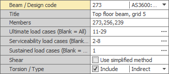
In this panel you can specify the beam number, design code, descriptive title, analysis member list, load case lists, shear method and torsion switch. The beam number and analysis member list are normally predefined based on which members you selected when you created the concrete beam, however you can change them here if required.
It is important that you correctly specify the load case lists and don't just leave them blank. The ultimate load cases are the ones that the strength design is based on and they are usually the combination load cases that have been factored up to ultimate. The serviceability load cases are used to calculate the short term deflections based on the cracked moments of inertia. They are usually the short term primary live load and wind load cases. Finally, the sustained load cases are used to calculate the long term deflections based on creep and usually consist of just the long term dead loads. Neither the serviceability or sustained load cases are used in the design calculations.
If you leave the ultimate load case list blank then all analysed load cases will be considered, whereas if you leave the serviceability or sustained load case lists blank then they will not be considered, effectively rendering them inactive.
It is up to you to set the ultimate, serviceability and sustained load case lists correctly. The program can't do it automatically for you.
For AS3600:2018 you can choose between the simplified (clause 8.2.4.3) or general (clause 8.2.4.2) methods for the shear calculations. Note that the AS3600:2009 version of the concrete beam design module always uses the simplified method.
If you wish to consider torsion then you should tick the "Torsion" checkbox. Enabling torsion requires extra longitudinal reinforcement to resist the torsion moment. For AS3600 you can specify "Indirect" torsion if torsional strength is not required for the equilibrium of the structure and the torsion in the beam is induced solely by the angular rotation of adjoining members. For further information refer to AS3600:2018 clause 8.2.1.2 or AS3600:2009 clause 8.3.2.
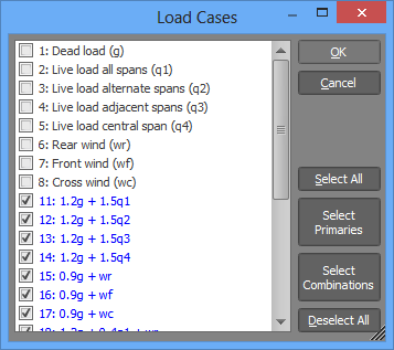
When specifying load case lists, you can either list them directly, or you can click the "..." button to display and select from a list of the load cases currently in the job as shown below.
Minimum design actions
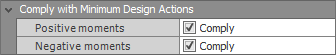
In order to guarantee a robust design, most concrete design codes impose lower limits on the design actions. You can comply with these limits for positive and/or negative moments.
Design priorities
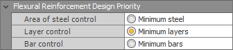
When performing a design, the module evaluates many solutions (sometimes hundreds), discards the impractical ones and then sorts the rest according to the "Design Priority" setting that you have selected. For example, if you have selected "Minimum bars" then it will put the solution that has the minimum number of bars first and present that as the optimal solution. "Minimum steel" gives the most efficient design in terms of total area of steel, however it usually results in many different bar sizes throughout the beam and so is often impractical. "Minimum layers" or "Minimum bars" give the best results in most circumstances.
Beam data panel
The information in this panel applies to the whole beam.
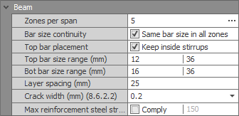
By default there are five "Zones per span", consisting of a zone at the supports at each end of the span plus three zones in the span. You can change the number of zones per span or, if you want different numbers of zones in some spans, you should click the "..." button and specify the number of zones in each span individually.
If you tick the "Same bar size in all zones" option then a bar that continues through multiple zones will maintain a constant size.
For "T" or "L" beams, if the top bars don't fit inside the stirrups and "Keep inside stirrups" is not ticked then the excess bars will be placed in the slab or flange.
During the shear design, the stirrups are kept at the size you specify and only their spacing is changed. The stirrup size is always constant for the entire beam.
The "Top and bottom bar size ranges" simply limit the size of bars that will be used in a design.
The "Layer spacing" is the centerline distance between bars in adjacent layers.
For AS3600, the desired "Crack width" can be set to 0.2mm, 0.3mm or 0.4mm as per tables 8.6.2.2(A) or (B) in clause 8.6.2.2.
For Australian maritime structures, the maximum allowable reinforcement steel stress at the serviceability limit state can be set and then checked against AS3997:2005 - "Guidelines for the Design of Maritime Structures".
For IS456, the "Effective width" of a "T" or "L" beam depends on whether the beam is integrated with a slab or is an isolated beam. For further information refer to IS456 clause 23.1.2.
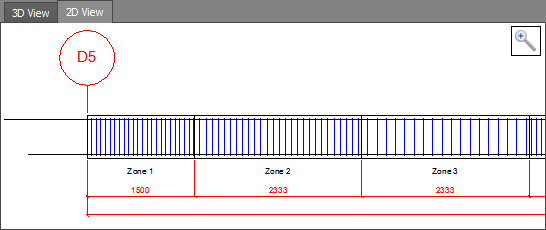
Zones
By default there are five zones per span, consisting of a zone at the supports at each end of the span plus three zones in the span. The number of zones per span can be changed in the beam data panel described above.
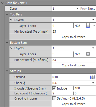
In the zones panel you can change the current zone by selecting it in the "Zone" field at the top or you can cycle through them by clicking the "Prev" or "Next" buttons. The current zone is highlighted in the beam view panel at the top, in the bending moment, shear force or deflection diagram in the middle, and in the cross section panel.
For each zone you can specify the number of layers, the bars per layer and the bar sizes. You can also specify the stirrup details and, for AS3600, the capacity reduction factor ϕ for shear in accordance with table 2.2.2 and the Vuc criterion for crack control in accordance with clause 8.2.4.5. Whenever you make changes to the reinforcement or layers, the changes are locked to guard against you doing an accidental design and losing your changes. If you really want to perform a design you must first unlock the beam before you can click the "Design" button as described in "Checking and Designing" above.
The "Minimum top/bot steel (% of max)" parameters place a lower limit on the area of steel in the current zone based on a percentage of the maximum area of steel used elsewhere in the beam. For example, if the maximum top area of steel in the beam is 2575mm^2 and you have specified a "Min top steel (% of max)" of 33% then the top area of steel for that zone will be limited to no less than 850mm^2.
The "Copy to all zones" buttons allow you to copy the data from the current zone to all other zones in the beam.
Development lengths
Development lengths are calculated automatically based on the bar size, bar type, end anchorage, concrete properties and bar stress. They are included in the reports and are displayed in the beam view panel. To see them more clearly you can turn them on or off in the beam view panel by clicking the "View development lengths" button.

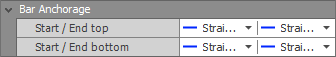
Bar anchorage
Bars can be left straight at the ends of the beam or they can be hooked or cogged.
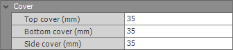
Cover
The cover is specified as the clear distance from the edge of the outermost bars and stirrups to the edge of the concrete.
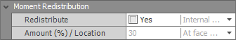
Moment redistribution
Moment redistribution allows you to reduce the bending moments at the supports with a resulting increase in the span moments. It is generally only applied to the internal supports of statically indeterminate beams, but you can also choose to redistribute the moments at the beam's end supports if appropriate. When moment redistribution is activated you must choose the amount of redistribution and specify whether that amount applies at the support centerlines or at the faces of the supports. During moment redistribution the shear forces are also adjusted to maintain static equilibrium.
Moment redistribution should be used with utmost care and if used inappropriately could result in unsafe designs. You should ensure that there is adequate rotation capacity in critical moment regions to allow the assumed redistribution of bending moments to be achieved.
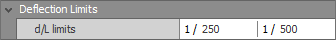
Deflection limits
In order to monitor deflections you can set d/L limits that will trigger warnings if they are exceeded. The d/L limits are also shown as colored lines in the deflection diagram so that you can visually see if they are exceeded or not. Note that the d/L limits are purely for your visual checking and are not used in the design calculations.
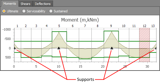
Support detection
The beam's supports are automatically detected based on node restraints and steps in the shear force diagram, however it is possible that for some beams, supports may be missed or non-existent supports may be detected. The supports are shown in the bending moment, shear force and deflection diagrams as small black triangles and so it is easy for you to visually see if they are correct or not.
Because the beam design or check relies on knowing where the supports are, it is imperative that the supports are correct before you accept any results.
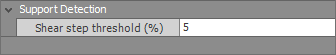
If a support occurs at a node that doesn't have a vertical node restraint, such as if the beam is supported on columns or other beams, it is detected by measuring the upwards step in the shear force diagram and if the shear step exceeds the "Shear step threshold" percentage then a support is assumed to exist at that location. The shear step threshold is determined by calculating the maximum shear force anywhere in the beam from all analysed load cases and then multiplying it by the threshold percentage that you specify. 5% has been found to produce good results, but if supports are being missed or non-existent supports are being detected then you should adjust the threshold until all the supports are found correctly.
Beam view panel
The panel at the top of the beam editor shows a 3D side view of the entire beam. By clicking on any part of the beam you can select a zone so that its reinforcement and other details are shown in the data panel on the left, and its dimensions and reinforcement are displayed in the cross section panel at the bottom of the editor.
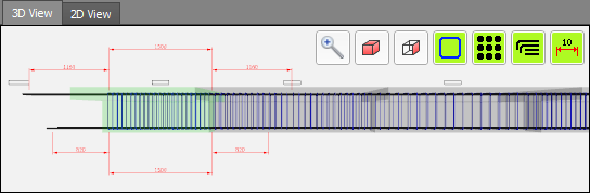
You can also zoom, pan and rotate the beam to show the dimensions, cross section and reinforcement in more detail.
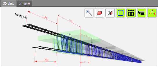
You can also click the "2D View" tab to display a 2D drawing of the beam.
The buttons at the top of the panel let you do a "zoom fit" or quickly switch to a 3D view or side view. You can also turn on/off the stirrups, main bars, development lengths or dimensions for a clearer view.
Moment, shear and deflection diagrams
The diagram in the middle panel by default shows the bending moment envelope for the ultimate load cases. By clicking the radio buttons at the top you can change it to show the envelopes for the serviceability or sustained load cases instead. You can also switch it to show shears or deflections by clicking the tabs at the top.
After a design, the critical zone is selected and is shown shaded in whichever diagram is displayed. You can also click on any zone in the diagram to select that zone so that its reinforcement and other details are shown in the data panel on the left, and its dimensions and reinforcement are displayed in the cross section panel at the bottom of the editor.
The green lines above and below the bending moment envelope represent the bending capacity of the beam and give a very good indication of how efficient your design is. The closer they track the bending moment envelope the more efficient your design is. Note however that if torsion is included then the capacity lines may overstate the bending capacity because some of the steel will be required to resist torsion and will not be available for bending. In this case there will be a gap between the bending moment envelope and the capacity lines, with the gap representing the reduction in bending capacity due to the torsion requirement. If minimum design actions govern then there may also be a significant gap between the capacity lines and the moment envelope.
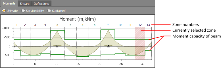
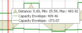
You can hover the mouse cursor over any part of the diagram to show the underlying values at the cursor's location.
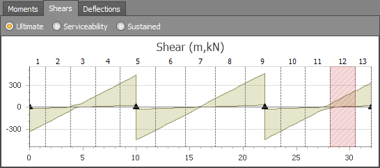
The shear tab displays the shear force envelope for the ultimate load cases.
The deflections tab displays the elastic, short term, long term and total deflections based on the "Serviceability" and "Sustained" load cases specified above the diagrams. The elastic deflections match the deflections from the SPACE GASS analysis and are based on the serviceability load cases using the gross (uncracked) moment of inertia (Ig). The short term deflections are also based on the serviceability load cases but using the cracked moment of inertia (Iefs), whereas the long term deflections are based on the sustained load cases using the moment of inertia adjusted for creep (Iefl). You can see graphs of Ig, Iefs and Iefl by clicking the "Ig, Ief" radio button. The total deflections are the sum of the short term and long term deflections.
Note that all deflections displayed in the diagram include the free body movement of the beam based on the elastic deflections of the supports and so if you are manually checking the total deflections by simply summing the short and long term deflections you must also subtract the deflections at the supports so that they are not doubled up. If your supports have short term or long term deflections that are significantly different to their elastic deflections, such as if the beam is supported on other beams for example, then you may need to adjust the short and long term deflections along the beam to allow for those support deflections.
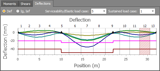
The lines below the deflection curves are based on the d/L limits you can specify in the data panel to provide an indication of whether the deflections are excessive or not. Note that the d/L limits are purely for your visual checking and are not used in the design calculations.
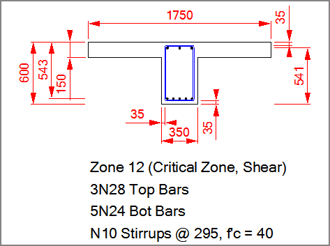
Cross section panel
The cross section panel shows the shape, dimensions and reinforcement for the currently selected zone. You can select a different zone by clicking it in the beam view panel at the top or by selecting it in the data panel on the left.
You can also click the "DXF/DWG" or "Save Image" buttons on the right side of the editor to export the cross section to a DWG or DXF file, or save the cross section image to a metafile (EMF) file. An EMF file can be used to generate a high quality image with no pixilation regardless of how much it is enlarged.


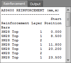
Reinforcement and output panel
The panel at the bottom-right shows a summary of the reinforcement for the entire beam. The "Start Position" column shows each location where a change in the bar size, number of bars or layers occurs. A single 0.000 indicates that the particular bars extend along the entire length of the beam.
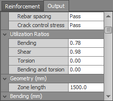
You can also click the Output tab to show a list of the main checks and variables used in the design/check.
Preferences
You can click the "Preferences" button to open the concrete beam preferences form and then change the defaults for various concrete parameters such as the default bar library, dimensions, clearances, zones, cover, size ranges, design priorities, code specific parameters, colors and other options.

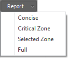
Reports
The reports button lets you generate various types of reports for the concrete beam. You can also generate reports for multiple beams via the "Concrete management tool".
Querying results
You can get a quick summary of the design results for any concrete beam by right-clicking on it and then choosing "Concrete Beam Design Results" from the popup menu that appears. While the query form is open you can click on any other beams to get their design result summaries too. For more information refer to "Query concrete beam design results".