Varying plate pressure loads
For retaining structures such as tanks or retaining walls, or structures subjected to other variable pressure distributions from wind and the like, the resulting pressure loads on plates can be generated using this tool. The pressure variation can be linear or based on an equation that you specify.
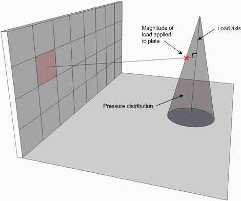
The tool works by you defining the pressure variation and a "load axis" along which the pressure distribution is defined. The pressure is then projected normal to the load axis onto each plate that you have selected.
The lateral position of each plate relative to the load axis is not important. For example, a plate a long way from the load axis will get the same pressure as a plate close to it. Similarly, a plate on one side of the load axis will get the same pressure as a plate on the other side.
For calculating the pressure on the walls of tanks or retaining structures, the load axis would normally be vertical and the pressure on a plate with its centre at height h would be the same as the pressure on the load axis at height h.
For other structures, such as a distribution of wind loads applied to a roof, it might be more convenient to have the load axis horizontal or maybe even parallel to the roof slope.
Plates that are beyond the ends of the load axis are not loaded. For example, if you have a tank that is 4m high and the load axis extends from the base of the tank vertically up to the 3m mark, the plates in the top 1m of the tank walls will not be loaded.

Load Axis and Pressure Distribution

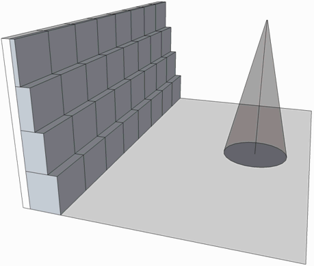
Resulting Pressure Applied to the Plates
If the pressure variation is defined by an equation, the equation must have "x" as the variable representing the distance along the load axis and can include any of the operators "+", "-", "*", "/", "\”, "%" and "^". It can also include any of the functions sin, cos, tan, asin, acos, atan, sqrt, factorial, abs, log, ln and exp.
For example, the pressure on the walls of a bulk solids container could be represented by the equation Pressure = g rc(1-e(-z/z0))/m, where, for a typical coal container could have values of g =10.8, rc=0.88, z0=4.03 and m=0.62.
This could be entered into the SPACE GASS equation field as
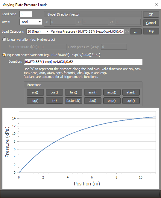
10.8*0.88*(1-exp(-x/4.03))/0.62, where "x" is the distance along the load axis and represents "z" in the original equation.
The procedure is as follows.
Select the plates you wish to load, click the right mouse button and then select "Loads" => "Varying Pressure Loads" from the popup menu that appears.
OR
Select "Varying Plate Pressure Loads" from the Loads menu, select the plates you wish to load, click the right mouse button and then click Ok.
Pick two points that represent the load axis along which the pressure variation will be distributed.
Remember that when picking points, you can use the mouse or you can simply type in the coordinates of the desired point(s). For more information, see "Positioning points using the keyboard".
In the form that appears (as follows), change the data to suit your requirements and then click the Ok button. The graph at the bottom of the form represents the shape of the pressure variation along the load axis.

The pressure variation can be linear for cases such as tanks subjected to hydrostatic loads or, for more complex profiles, can be defined by an equation that you specify as explained above.
If you specify "Local" axes then the pressure load will be applied in the local z-axis direction (ie. normal to the plane of the plate). If you specify "Global" axes then you must also specify a global XYZ vector that represents the direction of the pressure load.
The "Load category" field lets you specify which load category the generated loads will go into. For more information refer to "Load categories".
The pressure loads are then calculated and applied to the selected plates.
See also Plate pressure data.