The graphics window
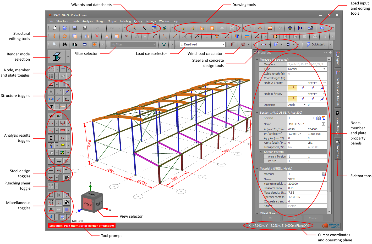
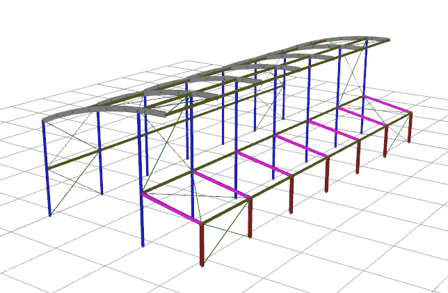
The graphics window is the heart of the program and is where you create, edit and view your model. Its layout and various functions are explained below.
Creating a model
A structural model can be created from scratch by using one of the "Structure wizards"  , the
"Portal frame builder"
, the
"Portal frame builder"  , "Datasheets"
 or by simply drawing nodes
  , members
 or plates
  ,
,  using their respective drawing tools. If you are new to SPACE GASS then a structure wizard is a good place to start, however if you want to experience the power and convenience of the graphical user interface then
drawing nodes, members or plates is the best way to go. It involves clicking one of the draw buttons , , or and then moving and
clicking anywhere in the graphics window to start drawing. There are various "Attachment and alignment methods" that let you position points precisely as you draw or you can simply type on
the keyboard to position a point. For more information, refer to "Drawing in the graphics window".
using their respective drawing tools. If you are new to SPACE GASS then a structure wizard is a good place to start, however if you want to experience the power and convenience of the graphical user interface then
drawing nodes, members or plates is the best way to go. It involves clicking one of the draw buttons , , or and then moving and
clicking anywhere in the graphics window to start drawing. There are various "Attachment and alignment methods" that let you position points precisely as you draw or you can simply type on
the keyboard to position a point. For more information, refer to "Drawing in the graphics window".
Rendering mode
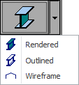
You can switch between wireframe, outline and rendered views of your model by clicking the render mode selection button.
Zoom, pan, rotate
You can zoom, pan or rotate your model via the mouse scrollwheel or by dragging it around using the left or right mouse buttons as shown below.
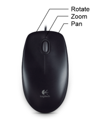
Zoom by rotating the mousewheel or by holding down the mousewheel while moving the mouse or by pressing the keyboard Up/Down arrow keys. If you find that zooming doesn’t work, click on the graphics area before trying again.
Pan by holding down the right mouse button while moving the mouse.
Rotate by holding down the left mouse button while moving the mouse. You can also drag the view selector (shown below) or click on one of its faces, edges or corners.
Note that if you find that the model rotates unintentionally when you are trying to select items or start a selection window, this is usually because you are moving the mouse while you click a point. You can improve this situation by increasing the "Rotation drag distance", making the rotation less sensitive to you moving the mouse while you click. If this doesn't fix the problem then you can set the "Require Ctrl key for viewport rotation" option. This setting requires you to hold down the Ctrl key in order to rotate the model. Both of these settings are available via the Settings menu => General Preferences.
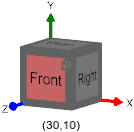
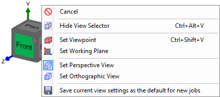
The view selector
An alternative to rotating the model by dragging it around directly is to drag the view selector around. You can also click one of the view selector faces, edges or corners to go straight to a specific viewpoint. If you click on the small square attached to the front face it will take you to the 30,10 viewpoint.
Note that you can also right-click one of the view selector faces to set the viewpoint to an exact angular position, change the working plane (or press X, Y or Z while you are working), switch between perspective and orthographic views, or save the current view settings as the default for new jobs.
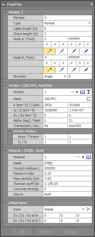
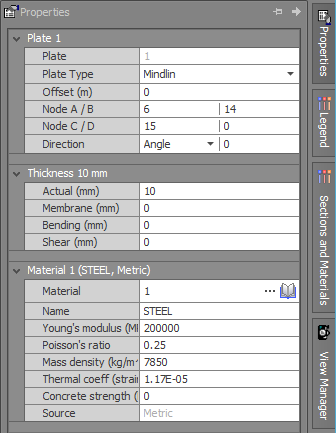
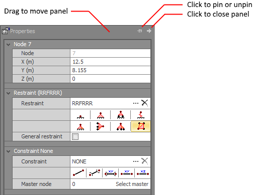
Node, member and plate property panels
The property panels operate in two slightly different modes as described below.
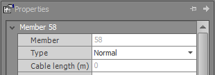
Mode 1 - When you double-click on a node, member or plate in the model, the appropriate property panel opens and you can make changes and then click the Ok button at the bottom of the panel to confirm the changes. Alternatively, if you make some changes in a property panel and then simply click on a another node, member or plate in your model, the previous changes will be confirmed and the newly selected item's data will appear in the property panel.
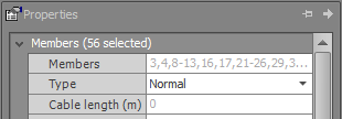
Mode 2 - If you select one or more nodes, members or plates and then right-click and select "View/Edit Properties (Form)" from the menu that appears, the appropriate panel will open with the combined data for all of the selected items. When in this mode, you cannot select other nodes, members or plates until you have clicked the Ok or Cancel buttons at the bottom of the panel. Blank fields indicate that the data is different for the selected items. Be careful with blank fields because if you enter data into one of them then all of the selected items will get that data.
|
Single selection
|
Multiple selection
|
|
|
|
|
|
|
|
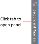
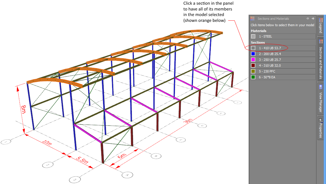
Sections and materials property panel
The sections and materials property panel is located by default on the right hand side of the renderer and is usually closed unless you have it pinned open. To open it simply click on the tab.
You can open the property panel to view the section and material properties and color match them to the members in your model, or you can click a particular section or material in the panel to have all the matching members in your model selected.
Controlling property panels
Property panels can be pinned open by clicking the button at the top of the panel so that it changes to  . This means that it will stay open, even if not being
used. If you click it again, it changes to
. This means that it will stay open, even if not being
used. If you click it again, it changes to  , indicating that the panel is not pinned and will close when not required.
If you want to close a panel manually then just click  .
.
You can undock a panel and place it anywhere on the screen or dock it to the left or right side of the renderer by first pinning it using and then dragging the
title bar of the panel to the desired location. Note that when undocked, it will stay open when not being used.
Drawing in the graphics window
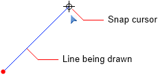
Once you are in a tool that involves drawing a line or vector, to begin drawing you must position your cursor at the start of the line, click the left mouse button, move the cursor to the other end of the line and then click the left mouse button again. The line is dragged around with the cursor as you position the second point. The end of the first line then becomes the start of the next line and the process continues for subsequent lines until you press Esc or click the right mouse button (right-click) to end the sequence.
There are a number of working plane, attachment, alignment and snap tools available to help you position points exactly where you want them while drawing or selecting points. These are explained as follows.
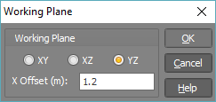
Working plane tool
At any time while drawing lines or just generally moving the mouse cursor, you can see its coordinates displayed in the bottom right-hand corner of the renderer. Depending on the current working plane, you will notice that only two of the coordinates
change as you move the mouse and the third one is held constant. You can change the working plane by pressing the X, Y or Z keys or by right-clicking one of the view selector faces or by clicking the working plane button ![]() in the bottom toolbar.
in the bottom toolbar.
Note that whenever you graphically select a point or a node, the working plane moves to the plane of that point or node. If you have a grid displayed (see below), it is drawn in the current working plane.
Attachment and alignment methods
The following discussion applies to all tools that involve selecting points or drawing vectors, such as when drawing nodes, members or plates, moving, stretching, copying, extending, connecting or even when adding dimensions. During these operations there are a number of aligning, snapping and attachment tools that can help.
To attach to a node (or the end of a member or the vertex of a plate), just move close to the node until it changes color. This indicates that you are close enough, and you can then click the left mouse button to attach to it.
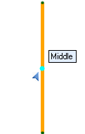
To attach to an intermediate point on a member, just move close to the member until it changes color. You can then move along the member to find its mid-point, third points, quarter points or fifth points, each of which will show up as a different colored dot with a label next to it. You can then click to attach to the desired point.
Note that if you wish to position a point close to a node or member without attaching to it, you can hold down the C key to temporarily turn off the attachment feature.
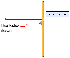
If you are drawing the second end of a line then "Perpendicular" and "Orthogonal" attachment points will also be highlighted on the member if applicable.
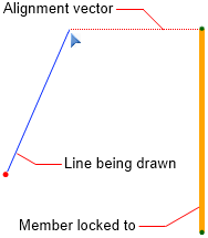
You can even align your point with an orthogonal line extending from a node or a member's midpoint. In order to do this you must first briefly hover over the node or member until you hear a faint pop sound that indicates that you have "locked on" to it. You can then move away and a dotted line will extend from the "locked on" node or member to your point, allowing you to line up with it exactly.
Note that you can temporarily turn off alignment with locked on nodes or members by holding down the A key while you are working. You can also change the "locked on" delay via the "Lock delay" setting in the Attachment and alignment methods Preferences form in the Settings menu (see below).
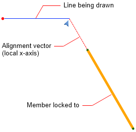
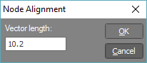
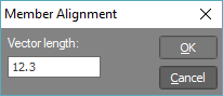
Similarly, you can align your point with any of the "locked on" member's three local axes as shown below.
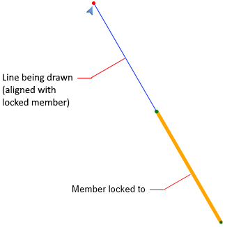
You can even use it to draw a new member that is aligned with an existing member by "locking on" to the existing member and then drawing in line with it.
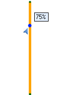
When aligning with a locked on node or member, you can position your point an exact distance from the locked on item by simply typing the distance rather than having to click the point with your mouse.
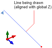
When drawing a line, if it is close to being aligned with one of the three global axes then it will snap to that axis. You can then either click the point with your mouse or you can just type the length of your line.
Note that you can temporarily turn off alignment with a global axis by holding down the A key while you are working.
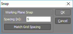
Snap tool
The renderer also has a snap tool which can be turned on or off via the snap button  in the bottom of the side toolbar or by pressing the S key. Note that "Attachment and alignment" tools also allow you to position points accurately without the need for the Snap tool in many instances.
Positioning points using the keyboard
If you can’t easily position a point using the mouse, you can simply type in the desired coordinates or length of the line you are drawing. As soon as you start typing, either of the following forms will appear automatically.
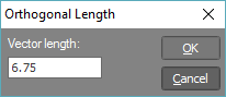
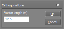
If you type while aligned with a member or global axis then the following form will appear, allowing you to enter the length of the line you are drawing.
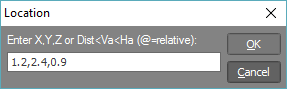
Alternatively, if you type while not aligned with anything then the following form will appear, allowing you to enter the coordinates of the point you are drawing to. Cartesian coordinates are assumed if you simply type the X, Y and Z values separated by commas. For example, 2.3,1.2,0.5 locates a point at X=2.3, Y=1.2 and Z=0.5. If you type less than three values for a point, the missing values are assumed to be zero. For example, 2.3,0,0 could be shortened to just "2.3", or 2.3,1.2,0 could be shortened to "2.3,1.2".
A point can also be entered using polar coordinates by typing a distance, followed by a vertical angle (upwards from the global horizontal plane), followed by a horizontal angle (forwards from the global vertical plane aligned with X). <’s are used to separate the values rather than commas. For example, a point 10 units from the origin with a vertical angle of 45 ° and a horizontal angle of 15 °, could be typed in as 10<45<15.
To enter points in relative mode (ie. relative to the other end of a line) apply an "@" prefix to the coordinates. For example, a point which is 8 units in the X direction and 6 units in the Y direction from a previous point, could be typed in as @8,6, or @10<36.9.
Note that in order to locate the "0,0,0" origin very quickly, you only have to type 0.
The following table summarizes the various ways you can use the keyboard to position points while drawing.
|
Type |
Situation |
Format |
Example |
|
Alignment vector length |
Locked to a node or member |
Length |
10.2 |
|
Drawn line length |
Aligned with a global axis |
Length |
6.75 |
|
Absolute cartesian |
Not locked or aligned |
X,Y,Z |
1.2,2.4,0.9 |
|
Relative cartesian |
Not locked or aligned |
@X,Y,Z |
@0,0,6.35 |
|
Absolute polar |
Not locked or aligned |
Length<VertAngle<HorAngle |
6.5<45<0 |
|
Relative polar |
Not locked or aligned |
@Length<VertAngle<HorAngle |
@10<30<0 |
Selection methods
You can select nodes, members or plates directly by simply clicking them with the left mouse button. In order to select multiple items you just keep clicking more items or you can use a selection window. You can also use a combination of direct clicking and selection windows. Other selection tools and shortcuts are described below.
Once your selection is complete you can click the right mouse button to show a menu of tools that can be used with the selected items. If you choose the "View/Edit Node/Member/Plate Properties (Form)" tool from the menu then the properties panel for the selected items appears, allowing you to view or edit them. This is a very handy way to make changes to a large number of items quickly. Alternatively, if you simply double-click (with the left mouse button) a node, member or plate then it goes straight to the properties panel for that item.
Selection windows
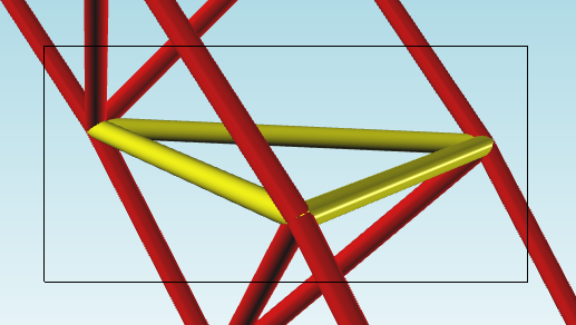
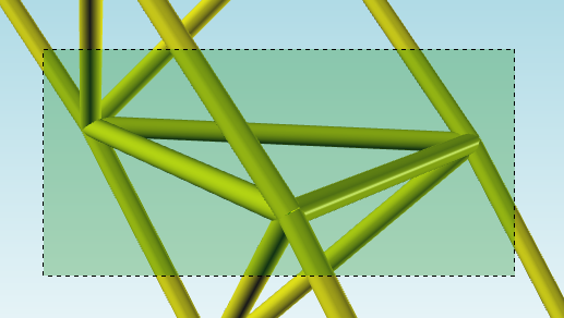
If the second corner of the selection is to the right of the first then it is a "Normal" selection window (shown as a rectangular outline) in which only the nodes, members or plates that fall completely within the window are selected. Alternatively, if the second corner is to the left of the first then it is a "Crossing" selection window (shown as a filled rectangle) in which any nodes, members or plates that are within the window or which cross the boundary of the window are selected. The two types of selection window are shown below.
Normal selection window - Only the items completely enclosed by the "normal" selection window are selected.
Crossing selection window - Items that are completely or partly enclosed by the "crossing" selection window are selected.
Forcing a selection window
It is often difficult to start a selection window if its first corner is over a plate because as soon as you click the first corner a plate gets selected instead. However you can force the start of a selection window by holding down the Shift key while clicking the first corner.
Deselecting items
In order to deselect nodes, members or plates, you simply select them again, either by clicking directly or by using a selection window.
Selecting all items
You can select all nodes, members or plates by using the Ctrl+A shortcut.
Selecting using the Find tool
You can use the Find tool to select nodes, members or plates. The Find tool can find and select items based on their numbering or their attributes. For more information, refer to the "Find" tool.
Inverting a selection
You can invert a selection (ie. select all the items that were not selected and deselect all the items that were selected) by using the Ctrl+I shortcut.
Selecting intersection nodes
You can select the nodes where members or plates intersect a plane of plates or where there is a change in direction of members by putting a selection window around the members or plates, right-clicking and then selecting "Select Intersection Nodes" from the popup menu that appears.
Selecting perimeter nodes
You can select the perimeter nodes around a plane that is defined by members or plates by putting a selection window around the members or plates, right-clicking and then selecting "Select Perimeter Nodes" from the popup menu that appears.
Selecting perimeter members
You can select the perimeter members around a plane that is defined by members or plates by putting a selection window around the members or plates, right-clicking and then selecting "Select Perimeter Members" from the popup menu that appears.
Selecting subdivided members
You can select all the segments of a subdivided member by holding down Ctrl+Shift and then clicking any segment of the subdivided member.
Selecting in-line members
You can select all the members that lie in a straight line and are connected to each other by holding down Ctrl+Alt and then clicking any member in the line. This is different to "Selecting subdivided members" because it continues past intersecting members that are not aligned with the selected member.
Selecting plates in a plane
You can select all the plates in a plane by holding down Ctrl+Shift and then clicking any plate in the plane.
Selecting plates bounded by members
You can select all the plates bounded by a perimeter of members by selecting the bounding members, right-clicking and then selecting "Select Plates Bounded by Members" from the popup menu that appears.
Creating a temporary selection filter
Once some items have been selected you can quickly create a temporary filter to make manipulation of the selected items easier. For more information, refer to "Hide selected items" and " Show selected items only".
Previous selections
You can cycle through your previous node, member and plate selections using Ctrl+R on your keyboard. Once you get to the desired selection you can just use it as though you had selected the items using the normal selection techniques. You can change the number of selections that are saved via Settings => General Preferences.
Selection shortcuts
Other selection shortcuts are listed at "Shortcuts".
Selecting a tool
Once you have made your selection, you can get access to the various graphical tools by right-clicking and then selecting from the menu that appears. A typical member selection menu is shown below.
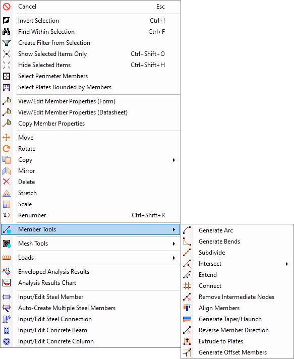
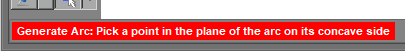
After selecting from the menu, the tool you selected may open a form or it may require you to pick extra points. For example, if you selected the "Generate Arc" tool from the above menu, the Arc tool would then require you to pick a point on the concave side of the arc so that it knows which direction to use when creating the arc. Whenever the graphical editor requires you to do something, it displays a red prompt at the bottom-left corner of the window as shown below. It is therefore a good idea to look there if you are not sure what to do next.
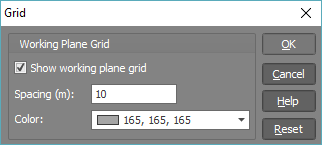
Grid tool
A grid can be displayed as a visual aid while you are developing or viewing your model. The grid also assists in identifying the working plane, as it is always displayed in that plane. The grid can be turned on or off via the grid button  in the bottom of the side toolbar or by pressing the G key.
Note that if you change your working plane (see above) then the grid automatically moves to that new plane.
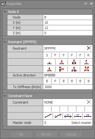
Restraints
Node restraints can be turned on or off in the renderer using the ![]() button in the side toolbar. Restraints are shown using combinations
of the following icons.
button in the side toolbar. Restraints are shown using combinations
of the following icons.
|
Icon |
Restraint |
Example |
|
|
3D fixed |
FFFFFF |
|
|
3D pinned |
FFFRRR |
|
|
2D fixed |
FFRRRF |
|
|
2D pinned |
FFRRRR |
|
|
1D translation fixed |
RFRRRR |
|
|
1D translation spring |
RSRRRR |
|
|
1D rotation fixed |
RRRRRF |
|
|
1D rotation spring |
RRRRRS |
Shortcuts
While using any of the renderer tools, various keyboard shortcuts are available that can speed things up. For a full list refer to "Shortcuts".
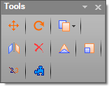
Customizing toolbars
All of the toolbars in the renderer can be hidden/shown, moved or undocked, and buttons can be added or deleted. For more information refer to Customizing Toolbars.
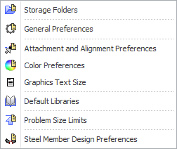
Renderer settings and preferences
Various settings and preferences are available from the Settings menu as shown below. Each of these is explained in detail in "Configuring SPACE GASS".
![]() If you have a large model with loads displayed and the renderer is operating slowly when you
zoom, pan or rotate, try turning off the loads display or at least select less load cases to be displayed simultaneously.
If you have a large model with loads displayed and the renderer is operating slowly when you
zoom, pan or rotate, try turning off the loads display or at least select less load cases to be displayed simultaneously.