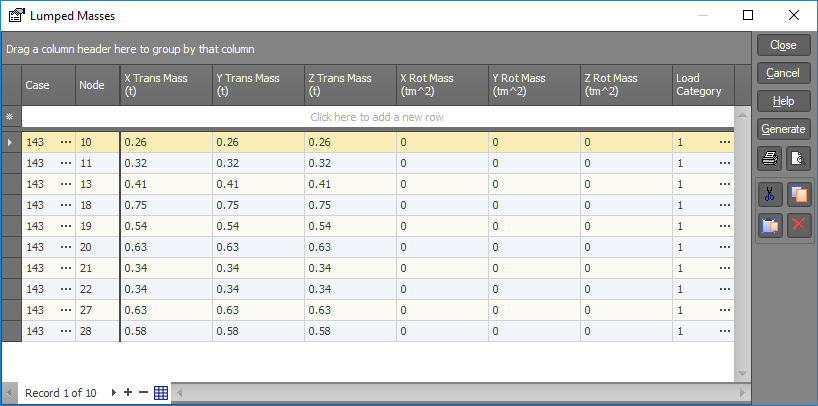
Lumped mass data
Lumped masses are considered in a dynamic analysis and are ignored in a static analysis. Translational or rotational masses can be applied to any node along or about the global X, Y and Z axis directions. If a mass is applied to a restrained degree of freedom then that mass is simply ignored during the dynamic frequency analysis.
Masses may be applied in any load cases and may be combined with static loads within the same load case, although it is often a good idea to put masses in load cases of their own (ie. not in with static loads) so that they can be isolated in graphics displays or output reports.
Self mass can be added to the lumped masses by either by adding self-weight to a load case that contains lumped masses or by combining lumped mass and self-weight load cases into a combination load case.
Case
Load case to contain lumped masses.
Node
Node to have masses applied.
X, Y and Z translational masses
Translational masses (global axes).
X, Y and Z rotational masses
Rotational masses (global axes).
Load category
The load category column lets you specify which load categories the loads will go into. For more information refer to "Load categories".
The application of lumped masses
A mass that affects the natural frequencies of a structure must be applied in each of the unrestrained directions of the node to which it is attached. For example, a 0.5 tonne machine which is attached to a point on a building rafter has an inertia in each of the X, Y and Z directions and effects the natural frequencies of the building in all three directions. It must therefore be applied as 0.5 tonne X, Y and Z translational masses.
! IMPORTANT NOTE !
Lumped masses are not the same as loads and therefore cannot be calculated by simply converting loads to mass units. Masses represent the structure and/or attachments to the structure which move and rotate with it and which effect its natural frequencies. Some types of loads would have to be input as lumped masses while others would not. For example, dead loads and 30-100% of live loads would normally affect the natural frequencies of a structure, however wind loads would not.
The inertia of the structure could be modelled in one of the following two ways:
Translational masses
Consider a rigid floor slab. You could model the distribution of mass by placing a small translational mass at each node in the slab (the sum of all node masses equalling the total mass of the slab).
Translational and rotational masses
You could also model the rigid floor slab by lumping all of the translational mass and a rotational mass at the centroid of the slab.
In the first approach, the rotational inertia would be provided by the action of each of the small translational masses being a distance away from the centroid of the slab. In the second approach, the rotational inertia would be provided directly by the rotational mass at the centroid of the slab. It is usually more convenient and just as accurate to use the second approach.
The rotational mass for a point at the centroid of a rectangle is
![]()
where m is the mass of the rectangle, and a and b are the dimensions of the rectangle.
The concept of rotational mass, together with formulae for calculating rotational masses at various locations on rectangles and other shapes, is given in Clough and Penzien (10).
Self mass
It is not necessary to manually input lumped masses for the self mass of the structure because self mass can automatically be considered by simply adding self-weight to one or more load cases. However, automatic self mass generation does not calculate rotational masses because of the large number of extra masses that would be generated for a fairly insignificant improvement in results accuracy. If required, rotational self mass must be manually applied as rotational lumped masses.
In order to adequately define the distribution of mass along members for which local vibrations are important, it is sometimes necessary to add intermediate nodes (with masses applied) to such members.
![]() The accuracy of a dynamic frequency analysis depends on correct placement of the master nodes.
Each master node must be placed as close as possible to the centre of mass of its slave nodes. If this is not done then the rotational inertia of the mass distributed to master nodes may not be accurate and this could affect the results of the dynamic
frequency analysis. Note that this only affects dynamic frequency analysis and is not a requirement for static analysis.
The accuracy of a dynamic frequency analysis depends on correct placement of the master nodes.
Each master node must be placed as close as possible to the centre of mass of its slave nodes. If this is not done then the rotational inertia of the mass distributed to master nodes may not be accurate and this could affect the results of the dynamic
frequency analysis. Note that this only affects dynamic frequency analysis and is not a requirement for static analysis.
See also Lumped masses text.
See also Self-weight.
See also Datasheet Input.
See also Lumped masses.
See also View diagrams.
See also Dynamic frequency analysis.
See also Running a dynamic frequency analysis.
See also Equivalent static seismic loads.