Node restraint data
The node restraint data is shown in the node properties data panel.
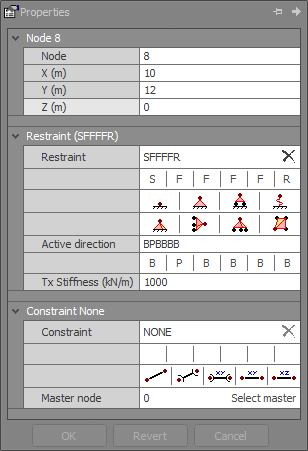
Node restraints are used to model the structure’s supports. They are sometimes referred to as boundary conditions.
Unrestrained nodes are generally free to move along or about any axis direction, however practical structures must be restrained to a footing in some way, otherwise instabilities would occur. The general rule with restraints is that if a node is connected to a footing or some other external support then it should have a restraint that limits some of its movements.
Nodes can be restrained about any of their six degrees of freedom and such a restraint may take the form of a fixed restraint, spring or non-linear restraint. Each type of restraint may have some additional data associated with it. For example, if a spring restraint is specified then a spring stiffness must also be input. Fixing a degree of freedom has the effect of immobilizing that node movement, while specifying a spring restraint causes the node movement to be a function of the spring stiffness.
Restraint codes
Node restraints are specified by a six character code corresponding to restraints along the global X, Y and Z axes, and about the global X, Y and Z axes respectively. Each character in the restraint code can be one of the following:
|
"F" = Fixed |
Prevents the node movement. |
|
"R" = Released |
Allows the node to move. |
|
"S" = Spring |
The node movement is dependent on an associated spring stiffness that you can specify. |
|
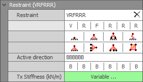
"V" = Variable spring |
Similar to "S", but there can be multiple spring stiffnesses that are related to how much node movement occurs. This is defined via a stiffness versus deflection table that you can specify. |
|
"P" = Plastic |
Imposes an upper force or moment limit on the restraint reaction. Node movement will only occur if the load exceeds the specified force or moment plastic limit. |
|
"N" = Friction |
Imposes an upper limit on the restraint reaction that is dependent on a specified proportion (ie. friction coefficient) of the reaction normal to the friction restraint. |
For example, a pin-based support that prevents all translations but allows the node to rotate about X, Y or Z would have a restraint code of FFFRRR. Alternatively, a roller support that allows the node to move in the X direction only and rotate about X, Y or Z would have a restraint code of RFFRRR. A fully built-in (encastre) support would have a restraint code of FFFFFF. A restraint that prevents movement in the Z direction while allowing all other movements and rotations would have a restraint code of RRFRRR.
Because variable spring, plastic, friction and one-way restraints are inherently non-linear in the way they behave, they require a non-linear analysis. However, if you run a linear static or buckling analysis, or a dynamic frequency analysis then SPACE GASS will permit it, but all of the non-linear restraints will be treated in a simplified linear manner that may not give you the results you expect or want. Plastic and friction restraints will be treated as fixed, while variable spring restraints will be treated as springs using a constant spring stiffness that corresponds with a zero deflection from its stiffness vs deflection table. One-way restraints will be treated a bi-directional.
In order to model a plastic, friction or one-way restraint that is fixed, SPACE GASS approximates it with a very stiff spring. The spring stiffness is set to 1.0e8 kN/m for a translational restraint or 1.0e8 kNm/radian for a rotational restraint. If you need to change these default stiffnesses (eg. if they are too stiff, resulting in ill-conditioning problems, or too soft, resulting in a significant translation or rotation at the node) you can override them via a text file. The text file should be called LargeStiffness.txt and created in your "C:\Users\<User name>\AppData\Local\SPACE GASS\14.20" folder. It should simply contain the translational and rotational stiffnesses in kN and metre units separated by a comma on the first line (eg. 1.0e8,1.0e8). Note that this procedure is different to normal bi-directional fixed restraints which are simply omitted from the stiffness matrix and therefore have infinite stiffness.
Variable spring, plastic, friction and one-way restraints will generally require more analysis iterations than fixed, released or spring restraints. This is because their stiffness has to be adjusted based on the displacements from the current iteration which, in turn, can cause significant changes to the displacements in the next iteration. This process continues until the changes in each iteration become quite small and fall within the requested analysis convergence accuracy.
! IMPORTANT NOTE !
Member end fixities should not be confused with node restraints. Member end fixities specify how members are connected to their end nodes, while node restraints specify how nodes are connected to the footings or other supports. Note that completely rigid frame members should have member end fixities of "FFFFFF" regardless of whether the frame has pin based supports or not.
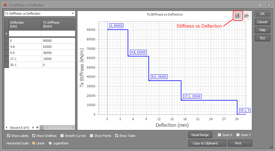
Variable spring restraints
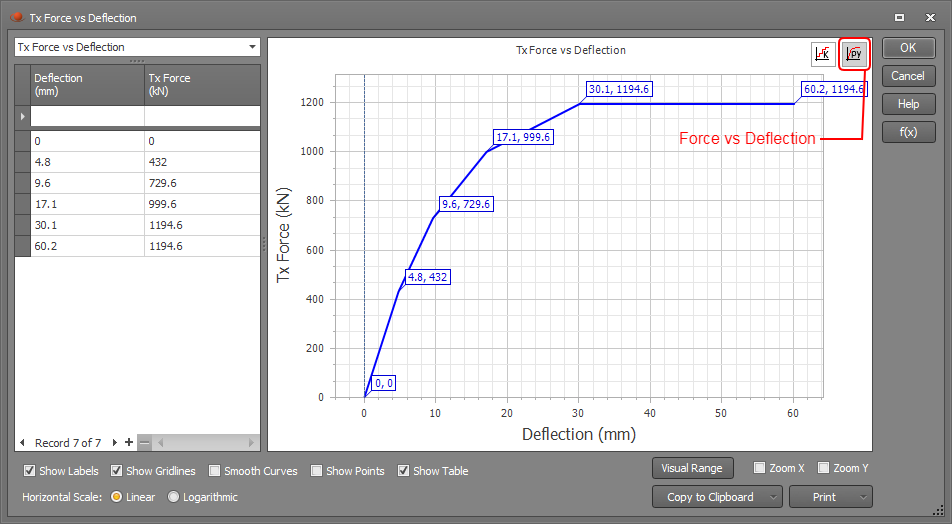
Variable spring restraints can be used when the spring stiffness changes depending on how much the node deflects or rotates. The variable spring data must be specified via a table that you can access by clicking the “Variable” button. Spring stiffness can be input as points along a stiffness vs deflection graph or a force vs deflection graph.
In the example shown below, the restraint code of VRFRRR is modelling a point along a pile where soil is resisting the pile from deflecting along the x-axis. In this example, the spring stiffness is 90000kN/m for deflections up to 4.8mm. As deflections increase, the stiffness steps down to 62000kN/m, 36000kN/m, 15000kN/m and finally 0kN/m for deflections that exceed 30.1mm.
If you haven't input any stiffness vs deflection data then the spring stiffness will be taken as zero.
Plastic restraints
Plastic restraints provide support up to a specified limiting force or moment. If the load exceeds the limiting force or moment then the restraint yields in a ductile manner and some movement or rotation of the node occurs.
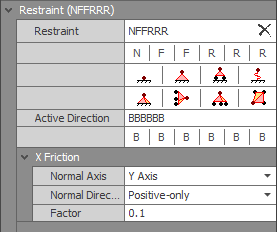
Friction restraints
Friction restraints can provide resistance that is dependent on the friction coefficient and the magnitude of the force acting normal to the friction plane. If the load in the friction plane exceeds the friction resistance then the restraint yields in a ductile manner and some sliding of the node occurs. For a friction restraint, you must also specify the direction and sign of the normal force, plus the friction coefficient. For example, to model a horizontal friction restraint in the X direction that has a sliding resistance capacity of 10% of the vertical load acting on it, you could use a restraint code such as NFFRRR, with an associated normal axis of Y, a normal direction of positive-only, and a friction factor of 0.1 as shown below. In this case, the normal direction of positive-only means that the friction restraint would only be effective when the reaction in the normal direction is positive (ie. when the vertical reaction is upwards or, in other words, when the vertical load is pushing down onto the friction plane). This prevents the friction restraint from being active if the vertical load is upward (ie. pulling away from the friction plane).
Note that the normal to the friction plane must also be restrained with an "F", "S", "V" or "P" restraint code, otherwise there would be no force pushing onto the friction plane.
One-way restraints
By default, restraints are bi-directional. This means that a restraint such as RFRRRR which prevents movement in the vertical (Y) direction would apply regardless of whether the load is up or down. Restraints that act in just one direction are also possible via the "Active direction" code. This code also has six characters which pair with the six characters of the restraint code. Each character in the active direction code can be one of the following:
|
"B" = Bi-directional |
The restraint acts in both directions. |
|
"P" = Positive-only |
The restraint acts in the positive direction only, which would result in a positive reaction force or moment. |
|
"N" = Negative-only |
The restraint acts in the negative direction only, which would result in a negative reaction force or moment. |
All restraint types (fixed, spring, variable spring, plastic or friction) can be bi-directional or one-way. For example, in order to model soil supporting a raft slab so that it resists downward movements but allows uplift, you could restrain each slab node with a restraint code of FSFRRR and an active direction code of BPBBBB. The "S" in the restraint code represents the vertical spring restraint provided by the soil, and the "P" in the active direction code means that the spring restraint will only act in the positive direction (ie. it will generate a positive vertical reaction). Because the restraint is one-way, it will be inactive in the areas of the slab that have uplift.
X, Y and Z axial stiffnesses
Axial spring stiffnesses are required for degrees of freedom restrained with "S" or "V". Axial spring stiffnesses must always be greater than zero.
When modelling the elastic properties of soil as a spring support, the spring stiffness is based on the modulus of subgrade reaction of the soil. This is a notoriously difficult parameter to get an accurate figure for. The following typical values of the modulus of subgrade reaction (to be used as a guide) are extracted from J. E. Bowles, "Foundation analysis and design", McGraw Hill 4th Edition, 1988.
|
Soil Type |
Modulus of Subgrade Reaction |
|
Loose sand: |
4800 - 16000 kN/m3 |
|
Medium dense sand: |
9600 – 80000 kN/m3 |
|
Dense sand: |
64000 – 128000 kN/m3 |
|
Clayey medium dense sand: |
32000 – 80000 kN/m3 |
|
Silty medium dense sand: |
24000 – 48000 kN/m3 |
|
Clayey soil with qu < 200 kPa: |
12000 – 24000 kN/m3 |
|
Clayey soil with qu in range 200 to 400 kPa: |
24000 – 48000 kN/m3 |
|
Clayey soil with qu > 800 kPa: |
> 48000 kN/m3 |
The spring stiffness to be input into SPACE GASS is simply equal to the modulus of subgrade reaction multiplied by the area of the footing that the spring is modelling. For example, if you have a 600mm wide strip footing supported on soil with a modulus of subgrade reaction of 80000 kN/m3 and the soil is modelled as springs spaced 500mm apart, the axial stiffness of each spring would be 80000 x 0.6 x 0.5 = 24000 kN/m. Units for the spring stiffness are shown in the headings of the node restraints datasheet.
X, Y and Z rotational stiffnesses
Rotational spring stiffnesses are required for degrees of freedom restrained with "S" or "V". Rotational spring stiffnesses must always be greater than zero.
Important note about restraining 2D frames
It is common practice amongst some engineers to restrain all out-of-plane movements in 2D frames. While this is generally appropriate for static analysis (provided there are no out-of-plane loads), it may not be appropriate for buckling and dynamic frequency analyses. This is because the frame may buckle or vibrate in an out-of-plane direction even though there are no loads in that direction. Of course, nodes that are braced in the out-of-plane direction should be restrained in that direction, however nodes that can move out-of-plane in the real structure should not be restrained in that direction in the model. Failure to do this could affect the buckling load factors, effective lengths and dynamic natural frequencies and mode shapes, and could result in unsafe designs.
For example, if a 2D frame rafter is sub-divided, the intermediate nodes should not be restrained in the out-of-plane direction unless they are braced in that direction in the real structure. Restraining them would prevent any out-of-plane buckling or vibration modes that could occur if the rafter member hadn’t been sub-divided.
Another example is a pin support for a 2D XY-plane frame column base which could be modelled with the standard 2D pin base restraint code of FFFFFR, however this would prevent rotations about the global X-axis. In reality, a column pin support would probably allow rotations about both horizontal axes and hence a restraint code of FFFRFR would be more appropriate. Restraining the rotation about the X-axis would affect the out-of-plane buckling and vibration modes of the column and could result in incorrect results.
See also Node restraints text.
See also Datasheet Input.
See also Node properties.
See also View node / member / plate properties.
See also Fix/release node degree of freedom tool .