Plate strip data
Plate strips are used to obtain deflections, bending moments, shear forces, axial forces and stresses along lines that can be drawn anywhere across the surface of a panel such as a slab or wall that has been modelled with plate elements.
The components of a plate strip are explained below. For information on creating and editing plate strips refer to "Plate strips".
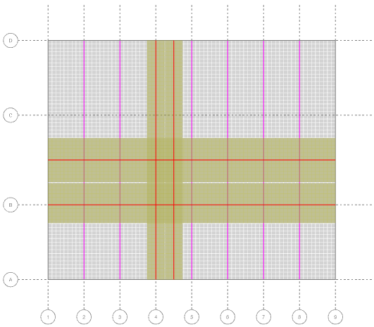
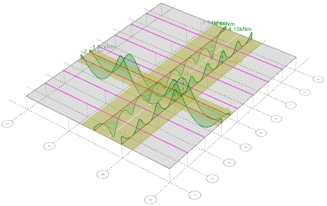
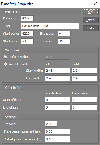
Plate strip
This is used to identify the plate strip and can be set to any number. It is set by default to match the start plate number for easy identification.
Title
The title can be used to describe and identify the plate strip.
Start plate
The plane of the plate strip is set to match the plane of the start plate. When drawing a new strip, you can set the start plate by hovering over it until it highlights and then drawing from one of its nodes. If you draw a plate strip from a node that is connected to plates that lie in different planes (eg. from the corner or edge of a box structure) then it is important that you select the correct start plate, otherwise your strip may finish up in the wrong plane. A strip in the wrong plane will become immediately obvious when you view it graphically.
End plate
This is the plate connected to the end of the strip.
Start and end node
These are the nodes that the plate strip is connected to. They must be connected to the start and end plates.
Width
You can specify a uniform width or a width that tapers or is different on the left and right sides of the strip. New strips default to a width of 1m if metric units are used or 3ft if Imperial units are used. See "Offsets" below for how to model a strip along the edge of a surface.
Offsets
Longitudinal offsets are used to shorten or lengthen the strip at either end, whereas transverse offsets are used to move the strip sideways. A positive transverse offset will move the strip to the left when looking from the start of the strip towards the end.
If you wish to place a strip along the edge of a panel, you could draw it along the edge and then apply transverse offsets to move it by half its width away from the edge. This is a better method than trying to specify a width of zero on the side of the strip that extends over the edge.
Stations
This is the number of equally spaced stations at which values are calculated along the strip in order to create the diagram. The smoothness of the diagram is dependent on the number of stations you choose, however the default of 200 is usually more than enough. Increasing the number of stations slows down the plate strip calculations and so if you are experiencing speed issues then you could try reducing the number of stations.
Transverse increment
The value for each station along the strip is calculated by integrating the values from the underlying plate elements across the width of the strip. The transverse increment is the step size used in the transverse integration. More accurate results are obtained with a smaller transverse increment, however this relies on interpolation and so decreasing the increment may not be beneficial or necessary if the mesh size is sufficiently small. Decreasing the transverse increment slows down the plate strip calculations and so if you are experiencing speed issues then you could try increasing the transverse increment.
If you see unexpected peaks or jumps in a plate strip diagram then this could indicate that the transverse increment needs to be reduced in order to provide more data sampling points for the diagram. This can be particularly evident in diagrams that aren't smoothed.
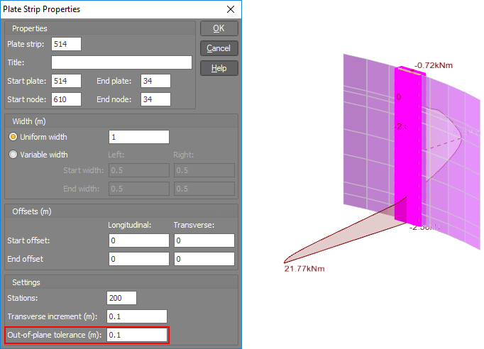
Out-of-plane tolerance
A plate strip diagram is calculated based on the values from the underlying plate elements that fall within the length and width of the strip. The out-of-plane tolerance allows you to eliminate any contribution from plate elements that are too far away in the out-of-plane direction from the plane of the strip. For example, if you have defined a plate strip for a slab on the second floor of a building, the out-of-plane tolerance eliminates any contribution from the plate elements in the first or third floors. Note that the out-of-plane tolerance is measured to a plate element's nodes and ignores any offset that the plate element might have.
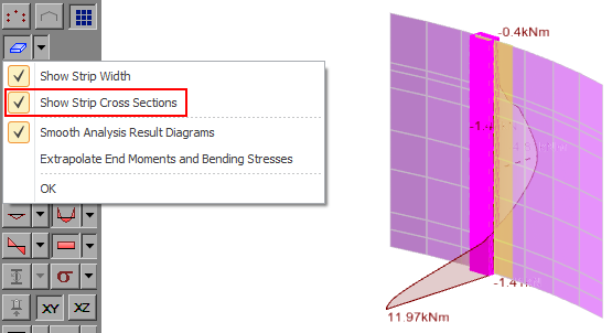
The "Out-of-plane" tolerance setting is very important to get right if you have a plate strip on a surface that isn't completely flat. In the following example we have a 1m wide vertical plate strip on the wall of a circular tank for which the contour diagram is indicating a moment at the bottom of 21.77 kNm/m. For our 1m wide strip we are expecting a moment at the bottom of 21.77 kNm, but the bending moment diagram is showing only 11.97 kNm, about half of what we are expecting.
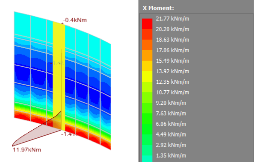
If we turn on the plate strip cross sections you can see that only half of the strip is active, indicating that not all the underlying plate elements are contributing to the bending moment diagram. In this case it is occurring because the plate elements in one half of the strip are in a slightly different plane to the ones in the other half due to the curvature of the tank wall.
If we increase the out-of-plane tolerance to allow for this then the plate strip shows the expected result.
This illustrates that when you have a plate strip on a surface that isn't completely flat, it is very important that you turn on the strip cross sections to check that all of the strip is active before you accept its results.
Wood-Armer moment adjustment
When displaying bending moment diagrams for plate strips they can optionally be adjusted to take into account the effect of twisting on the bending moments. The procedure for adjusting My (the moment about an axis across the strip) is as follows:
1. For each station along the strip the Mx, My and Mxy values are summed from the plate elements across the strip to obtain a single Mx, My and Mxy value at the strip station.
2. For bottom reinforcement, if Mx > -|Mxy| then My = My + |Mxy|, otherwise My = My + |Mxy2/Mx|. In either case My >= 0.
3. For top reinforcement, if Mx < |Mxy| then My = My - |Mxy|, otherwise My = My - |Mxy2/Mx|. In either case My <= 0.
This has the effect of amplifying the positive and negative moments. For more information refer to "Sign conventions".
See also Plate strips.
See also Plate strips text.
See also View plate strips.
See also Datasheet Input.