Sign conventions
Items which act along or about an axis are considered to be positive when they act along or about the positive axis direction. Positive rotations conform to the right hand screw rule shown as follows.

Right Hand Screw Rule
Applied loads have their sign determined by the axes system in which they are referred. Most types of member and plate loads can be specified in either the global or local system, however node loads and self weight are always referenced by the global system.
Node displacements are positive if they displace along or around the positive global axis directions. External reactions are positive if they act along or around the positive global axis directions.
Member Actions
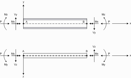
Member actions follow the sign conventions as follows.

Member Forces and Moments
Positive axial forces cause compression in the member.
Positive moments cause compression on the positive axis side of the member.
![]() Channel and angle sections have their flange toes pointing in the direction of the local z-axis.
Positive y-axis moments therefore cause the flange toes to go into compression.
Channel and angle sections have their flange toes pointing in the direction of the local z-axis.
Positive y-axis moments therefore cause the flange toes to go into compression.
Positive shears cause the node A end of the member to translate in the direction of the positive axis with respect to the node B end.
Positive torsions cause the node A end of the member to rotate anti-clockwise with respect to the node B end when observed from the node B end.
Plate Actions
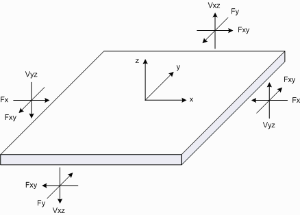
Plate actions follow the sign conventions as follows.

Plate Forces

Plate Moments
![]() When calculating the design moments for reinforced concrete slabs, the twisting moment Mxy
must be combined with the normal bending moments Mx and My. The Wood-Armer method is commonly used for this and is explained in "Bending Moments in Reinforced Concrete Slabs" below.
When calculating the design moments for reinforced concrete slabs, the twisting moment Mxy
must be combined with the normal bending moments Mx and My. The Wood-Armer method is commonly used for this and is explained in "Bending Moments in Reinforced Concrete Slabs" below.

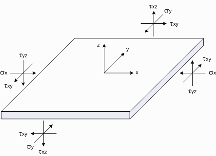
Plate Stresses
![]() Note that plate elements have no rotational stiffness about their local z-axis. This means
that there is effectively a rotational pin connection between the plate and its corner nodes about the axis normal to the plate.
Note that plate elements have no rotational stiffness about their local z-axis. This means
that there is effectively a rotational pin connection between the plate and its corner nodes about the axis normal to the plate.
Positive moments cause compression in the top (positive z-axis) face of the plate.
Plane Stress
Three dimensional objects subjected to loads generally have three principal stresses, however in structural elements where one dimension is very small compared to the other two (ie. plate elements), one of the three principal stresses is zero and a state of "plane stress" is said to exist. In this case, the stresses are negligible with respect to the smaller dimension as they are not able to develop within the material and are small compared to the in-plane stresses.
Principal Stress
For plates subjected to plane stress, there are two principal stresses acting in the principal axis directions. The angle between the principal axes and the local x and y axes is called the principal angle. The principal stresses can be calculated from sx, sy and txy using Mohr circle theory as follows.
s1 = ( sx + sy)/2 + SQRT(( sx - sy)2/4 + txy2)
s2 = ( sx + sy)/2 - SQRT(( sx - sy)2/4 + txy2)
txymax = ( s1 - s2)/2
f = Tan-1(2 txy/( sx - sy))/2
where sx, sy and txy are the membrane and shear stresses in the local axis directions (as per the above diagrams), s1 and s2 are the principal stresses, txymax is the maximum shear stress and f is the principal angle.
von Mises Stress
Richard von Mises (an eminent Austrian scientist who worked on solid mechanics, fluid mechanics, aerodynamics, aeronautics, statistics and probability theory) found that, even though none of the principal stresses exceeds the yield stress of the material, it is possible for yielding to result from the combination of stresses. The von Mises criteria is a formula for combining these principal stresses into an equivalent stress, which is then compared to the yield stress of the material. The yield stress is a known property of the material and is usually considered to be the failure stress.
The equivalent stress is often called the "von Mises Stress" as a shorthand description. It is not really a stress, but a number that is used as an index. If the von Mises stress exceeds the yield stress, then the material is considered to be at the failure condition.
The von Mises stress can be calculated from the principal stresses according to:
svm = SQRT((( s1 – s2)2 + s12 + s22)/2)
where s1 and s2 are the principal stresses and svm is the equivalent or "von Mises" stress.
Bending Moments in Reinforced Concrete Slabs
When evaluating the design moments for a reinforced concrete slab, the twisting moment Mxy must be taken into account in addition to the normal bending moments Mx and My. Mxy contributes a moment effect to both the principal bending directions x and y.
Using the Wood-Armer method, the design moments Mx* and My* can be determined as follows:
To design bottom reinforcement (ie. calculate moments that cause tension in the bottom face):
Mx* = Mx + | Mxy |
My* = My + | Mxy |
If either of Mx* or My* from the above calculations are < 0 then
If Mx* < 0 then Mx* = 0 and My* = My + | Mxy2/Mx |
If My* < 0 then My* = 0 and Mx* = Mx + | Mxy2/My |
To design top reinforcement (ie. calculate moments that cause tension in the top face):
Mx* = Mx - | Mxy |
My* = My - | Mxy |
If either of Mx* or My* from the above calculations are > 0 then
If Mx* > 0 then Mx* = 0 and My* = My - | Mxy2/Mx |
If My* > 0 then My* = 0 and Mx* = Mx - | Mxy2/My |
![]() SPACE GASS reports include the Wood-Armer adjusted moments (as Mxt, Mxb, Myt and Myb), plus
the adjustment is available in the reinforced concrete slab design module and when displaying bending moment diagrams in plate strips. For more information refer to "Plate strip data", "
Plate strips" and "Concrete slab design".
SPACE GASS reports include the Wood-Armer adjusted moments (as Mxt, Mxb, Myt and Myb), plus
the adjustment is available in the reinforced concrete slab design module and when displaying bending moment diagrams in plate strips. For more information refer to "Plate strip data", "
Plate strips" and "Concrete slab design".
Further information can be found by searching for "Wood-Armer" on the Internet or at web sites such as http://www.scribd.com/doc/76706580/Slab-Design-by-Wood-Armer-Method or http://www.scribd.com/doc/51463621/Wood-Armer
Axes in Steel Member Design
If the cross section is not transposed (the usual case) then the steel member design module treats the local z-axis of the member as the cross section's major axis. If it is transposed then it treats the local y-axis as the major axis.
If Imajor < Iminor then the steel member design module will display an error message.
If the cross section has been rotated or mirrored in the shape builder then you can’t use it in the steel member design module. If you want to rotate the cross section and still use it in a steel member design then you should do it as a direction angle, direction node or direction axis in the member properties data.