Member data
Members represent the actual beams, columns, ties, struts, cables, braces, etc. in the real structure. They must be prismatic and must be connected to a node at each end.
Member
The member numbering order affects the analysis frontwidth, however this is of no consequence if the wavefront optimiser is used. The graphical renumbering tool also means that the initial member numbering order is unimportant because it can be easily changed at any time. Successive member numbers do not have to be sequential.
Type
|
Choices are: |
Normal |
|
|
Tension-only |
|
|
Compression-only |
|
|
Cable |
|
|
Gap |
|
|
Brittle fuse |
|
|
Plastic fuse |
Tension-only and compression-only members
While in tension, tension-only members act identically to normal members with axial, flexural, torsional and shear capacity. However, if they go into compression then they are automatically disabled and act as if they have been removed from the model. Members such as tension bracing and slender ties fall into this category.
While in compression, compression-only members act identically to normal members with axial, flexural, torsional and shear capacity. However, if they go into tension then they are automatically disabled and act as if they have been removed from the model (ie. they have no axial, torsional, shear or bending stiffness). This type of member is useful in situations such as where a support member resists download loads by bearing on a footing but is unable to resist any uplift.
In both tension-only and compression-only cases, the program does an initial analysis and then scans for tension-only members that have gone into compression, and compression-only members that have gone into tension. If any of these are found they are disabled and the structure is re-analysed. This process continues until all tension-only members are in tension and all compression-only members are in compression. Note that disabled members are sometimes re-enabled if their axial force reverses sign during the iteration process.
![]() Slender members that rely on axial tension to resist lateral loads applied to them should be modelled as cables rather than as tension-only members!
Slender members that rely on axial tension to resist lateral loads applied to them should be modelled as cables rather than as tension-only members!
![]() During a dynamic analysis, tension-only and compression-only members are treated as normal
members that can take tension and compression.
During a dynamic analysis, tension-only and compression-only members are treated as normal
members that can take tension and compression.
See also Tension-only and compression-only effects.
Cable members
Cable members use axial tension only to resist lateral loads. They have no flexural, torsional or shear capacity, and so to avoid instabilities you must restrain all rotational degrees of freedom for nodes connected to cable members which are not rotationally fixed to other members. Cable end fixities of FFFFFF, FFFFFR, FFFFRR, FFFRRR all give the same results.
Cables that aren’t laterally loaded are treated as tension-only members which become disabled if they go into compression. Laterally loaded cables sag instead of taking compression.
Cable length
If the member type is "Cable" then an unstrained cable length can be specified to allow for cable sag when the cable length is different to the chord length (as follows). A zero cable length indicates that the unstrained cable length is equal to the chord length.
![]() Cable members cannot be included in a dynamic analysis.
Cable members cannot be included in a dynamic analysis.
See also Cable members.
Gap members
Gap members can be used to model situations where one part of a structure bears on another after a certain relative displacement. You can specify separate tension and compression gaps. Axial force will be developed in the member if it lengthens by more than the tension gap or if it shortens by more than the compression gap.
Brittle fuse members
Brittle fuse members can be used to model members that fail axially in a non-ductile manner at a specified limiting axial force. You can specify separate tension and compression limiting axial forces. The axial force in the member will become zero if its tension or compression limit is exceeded.
Plastic fuse members
Plastic fuse members can be used to model members that yield axially in a ductile manner at a specified limiting axial force. You can specify separate tension and compression limiting axial forces. The axial force in the member will remain constant at the specified limit if its tension or compression limit is exceeded.
Some extra points to note for gap and fuse members are as follows:
-
Gap and fuse members behave like normal members in terms of bending, shear and torsion, however they do not exhibit any P-delta behaviour and will not buckle under axial load.
-
A tension or compression limit of zero in a fuse member will be treated as no limit. For example, if you specify a tension limit of zero and a compression limit of 10kN, the fuse member will be able to resist compression up to a limit of 10kN, but will have unlimited tension capacity. If you wanted it to have no tension capacity then you would have to specify a very small tension limit such as 1.0e-6 rather than zero. The compression limit is treated in a similar way.
-
In some situations, a fuse limit will not be achievable if there is no alternative load path for the excess axial force. For example, consider a simple column with a 10kN fuse limit which is supported at the bottom and free at the top. If a 20kN vertical load is applied at the top then the axial force in the column will always be 20kN regardless of the fuse limit. In cases like this the analysis won't be able to find a solution and therefore won't converge.
-
If loads are applied directly to a fuse member that cause its axial force to be different at each end then the final axial force may exceed the fuse limit at one end and be less than the fuse limit at the other end. For example, if you have a column with a self-weight of 2kN, the axial force at the bottom will be 2kN more than the axial force at the top due to the self-weight distribution. If this was a fuse member with a compression limit of 10kN then the axial force at the bottom would be 11kN and the axial force at the top would be 9kN. This also applies if member concentrated or distributed loads are applied to a fuse member which affect its axial force.
-
Because gap and fuse members are inherently non-linear in the way they behave, they require a non-linear analysis. However, if you run a linear static or buckling analysis, or a dynamic frequency analysis then SPACE GASS will allow it, but all gap and fuse members will be treated in a simplified linear manner that may not give you the results you expect or want. They will be treated like normal members with their tension and compression limits ignored.
-
Gap, fuse, tension-only and compression-only members will generally require more analysis iterations than normal members. This is because they have to be enabled/disabled or their stiffness has to be adjusted based on the displacements from the current iteration which, in turn, can cause significant changes to the displacements in the next iteration. This process continues until the changes in each iteration become quite small and fall within the requested analysis convergence accuracy.
Chord length
The chord length is the straight line distance between the member ends. Note that a member’s chord length may not be equal to the distance between it’s end nodes if offsets exist for that member.
Using a direction angle, node or axis
If a direction angle, node or axis is defined then the member is rolled about it’s longitudinal x-axis by the direction angle or, if a direction node or axis is defined, by an amount such that the local y-axis is aligned with the direction node or axis as shown below.
Note that the three member orientation members are mutually exclusive. Hence, setting one of them to a desired value causes the other two to be disabled.

Member Local Axes
Direction angle
The direction angle (degrees), also called the skew angle, allows you to roll the member (with its local axes) about it’s longitudinal axis. It is normally set to zero so that the member local y-axis lies in a vertical plane.

Member Direction Angle
Direction node
Selecting a direction node aligns the local xy-plane with the nominated node.
A direction node can be a normal node or a dummy node (one which is not connected to any members).

Direction Node
Direction axis
|
Choices are: |
X axis, |
|
|
Y axis, |
|
|
Z axis, |
|
|
-X axis, |
|
|
-Y axis, |
|
|
-Z axis, |
|
|
N/A. |
Selecting a direction axis aligns the local xy-plane with the nominated axis (eg. -Z axis selected in the diagram as follows).

Direction Axis
If you are unsure of the orientation of the local axes for a particular plate, you can display them graphically (see also View local axes).
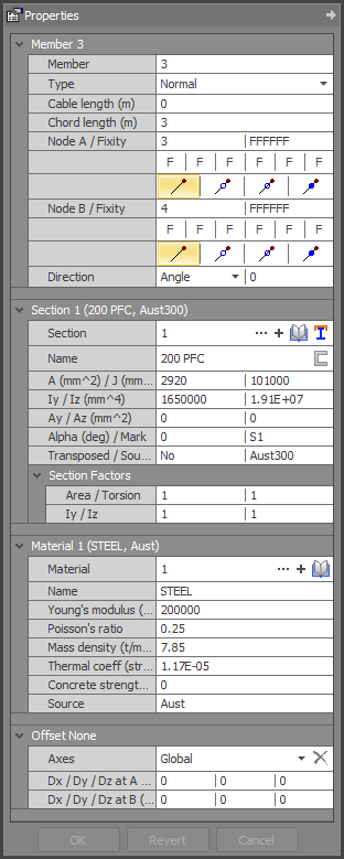
Node A and B
The two end nodes connected to each member are referred to as node A and node B. Node A is considered to be at the start of the member and any external loads applied to the member are located by their distance from node A.
Node A cannot be equal to node B, however there are no restrictions relating to node A being numerically bigger than node B or vice-versa.
End fixity
A member may be released or fixed to its end nodes with varying degrees of fixity. Member end fixity is referenced by the local axes system and there are six possible components at each end which may be fixed, released or connected with a spring. These components are specified by a six character code corresponding to translational fixity along x, y and z and rotational fixity about x, y and z respectively.
An "F" represents fixed, "R" represents released and "S" represents spring. For example, a pin ended truss member with no rotational end fixity in a 3D frame could be modelled using a fixity of "FFFFRR" at each end (or FFFRRR if the torsions are also released), while a pin ended truss member in a 2D frame could have fixities of "FFFFFR". Members in a rigid jointed frame would have fixities of "FFFFFF".
"S" fixity codes allow you to model translational springs (along local x) or rotational springs (about local y or z) at the ends of a member. If you specify a spring stiffness in the fixity code you will also need to enter a corresponding stiffness in the matching stiffness fields.
! IMPORTANT NOTE !
Member end fixities should not be confused with node restraints. Member end fixities specify how members are connected to their end nodes, while node restraints specify how nodes are connected to the footings or other supports. Note that completely rigid frame members should have member end fixities of "FFFFFF" regardless of whether the frame has pin based supports or not.
Section
The section property number references a particular member cross section from the section property data. Thus, members with identical section properties would have the same section property numbers.
The current section property for the members selected is displayed in this field. If no section property has been chosen, or if more than one section property applies to the selection, this field will be blank. The source is displayed along with an indication of whether the section has been flipped and what type of angle section was chosen (if appropriate).
You can change the section property by entering another section property number. If this number corresponds with a section which has already been defined, the corresponding properties will be displayed. All of the members selected will have this property applied to them.
Material
The material property number references a particular material from the material property data. Thus, members with identical materials would have the same material property numbers.
![]() For full details of the forces and moments in members, refer to "Sign conventions".
For full details of the forces and moments in members, refer to "Sign conventions".
See also Section properties.
See also Material properties.
See also Member offsets.
See also Members text.
See also Datasheet Input.
See also Member properties.
See also Draw.