Section property data
The section property data is shown in the member properties data panel.
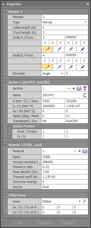
Section properties must be input for each type of member cross section in the model. Each section property describes the geometric properties of a single cross section relative to the local member axes.
Section
There are two fields, one for the section property number and the other for the section name. Section property numbers do not have to be sequential or in any particular order. The section property name is used as a description for the section, and as a reference for sections which have been read from a library.
Source
This indicates the source of the section. There are four different sources:
|
Manual: |
User defined properties. |
|
Library: |
A shape taken from a library. The source will be the library name (eg. AUST300). |
|
Shp Bldr: |
Section defined in the Shape Builder. |
|
Std Shps: |
Section defined in Standard Shapes. |
See also Standard sections libraries.
See also Shape builder.
![]() If you create a section in the shape builder by importing it from the library, and you don’t
make any changes to it, the source will be the name of the library the section was taken from. However, you can still edit the shape via the shape builder. You can also edit other library sections in the shape builder, even if the section wasn’t input
via the shape builder.
If you create a section in the shape builder by importing it from the library, and you don’t
make any changes to it, the source will be the name of the library the section was taken from. However, you can still edit the shape via the shape builder. You can also edit other library sections in the shape builder, even if the section wasn’t input
via the shape builder.
Transposed
"YES" if the section has been transposed (see also Transposing a section).
Angle Type
Indicates the angle configuration.
|
Choices are: |
Single, |
|
|
Short-Short, |
|
|
Long-Long, |
|
|
Starred. |
See also Angle sections.
Area of section
Cross sectional area of the section.
Torsion constant
Torsional stiffness of the cross section. Calculating the torsion constant for arbitrary cross sections can be quite complex, particularly if the cross section changes shape (warps) under torsion. For example, a circular tube has a relatively high torsion constant because it doesn’t warp under torsion. However, if a saw cut is made through the tube wall the torsion constant is drastically reduced because the cross section can change shape under very small torsion loads. Thus two shapes with very similar geometric properties can have substantially different torsion constants.
The Shape Builder features two methods for calculating torsional properties: a basic calculator and a finite element (FEM) calculator.
The basic calculator quickly determines torsion constants using established formulas for specific individual shapes. It then approximates the torsional constant for multiple shapes by summing these individual constants.
The more precise, though slower, FEM calculator computes the torsional constants of connected shapes using the finite element method. This method is based on the theory presented by Walter Pilkey in "Analysis and Design of Elastic Beams: Computational Methods."
![]() The torsion constant for shapes which cannot warp is equal to the polar moment of inertia.
The torsion constant for shapes which cannot warp is equal to the polar moment of inertia.
Y and Z moments of inertia
Principal moments of inertia of the cross section.
Y and Z shear areas
Principal shear areas of the cross section, where a value of zero represents an "Infinite" shear area.
The shear area is the effective cross sectional area which is used in the calculation of shear deformations. In general, the shear area depends upon the shearing stress distribution, which in turn depends upon the shape of the cross section.
For rolled steel sections, the major axis shear area is approximately equal to the area of the web(s). For rectangular cross sections, the shear area is equal to A/1.5, where A is the gross area. Values for other shapes are given in standard textbooks on strength of materials.
![]() For most cross sections and materials, the shear deformations are negligible compared to the
flexural deformations. Therefore, the shear area can often be specified as infinite.
For most cross sections and materials, the shear deformations are negligible compared to the
flexural deformations. Therefore, the shear area can often be specified as infinite.
Principal angle
Angle (degrees) from principal axes to geometric axes in anti-clockwise direction. For example, the principal angle is positive for single angle sections that have their horizontal leg pointing to the left.
Section mark
Member mark used in connection detail drawings, marking plans, etc.
Section factors (new in v12.60)
In order to model cracked section properties in reinforced concrete members you can specify section factors for the cross sectional area, torsion constant and the two principal moments of inertia. Any members that reference a section property with section factors other than 1.0 will use the adjusted section properties in the analysis and design modules. Note that section factors do not affect a section's dimensions or the way it is shown graphically.
If section factors other than 1.0 are specified then the analysis is carried out as normal, but with the area, torsion constant and moments of inertia multiplied by their appropriate factor. Bending stresses calculated post-analysis are based on M.y / I, where M is the bending moment from the analysis, y is the depth to the extreme fibre and is not affected by the section factor and I is the factored moment of inertia.
Note that in SPACE GASS 14.00 and earlier versions an area section factor other than 1.0 affected the member's axial stiffness and self-weight. This was changed in SPACE GASS 14.10 and future versions to only affect the axial stiffness and not the self weight.
Section factors can also be applied to non-concrete members and it is up to you to determine if this is appropriate. If section factors other than 1.0 are used with steel members then any code checks done in the steel design modules will be unaffected, however the design actions used will have changed due to the effect of the section factors on the analysis.
See also Section properties text.
See also Datasheet Input.
See also Member properties.
See also Plate properties.