Creating and editing concrete columns
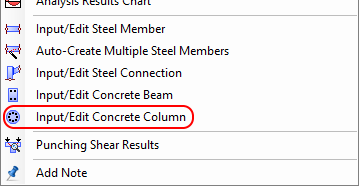
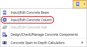
In order to define a concrete column, it is simply a matter of selecting the members that make up the column, clicking the right mouse button and then selecting "Input/Edit Concrete Column" from the menu that appears or by clicking the  button in the top toolbar and then selecting "Input/Edit Concrete Column".
Note that the reinforced concrete column module does not let you input the cross section shape or dimensions. The cross section geometry is taken from the column's section properties and must have been defined earlier by you using the shape builder.
The column is then designed and the results are presented in the concrete column editor shown below.
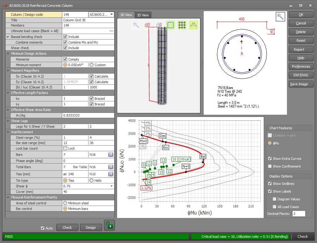
From there, you can examine the column, click the Ok button to save and exit if you happy with it, or make changes to customize it to your exact requirements.
The status bar
The status bar at the bottom of the editor indicates whether the column has passed, failed or passed with a warning. It includes the critical load case, the utilization ratio and a brief explanation of the failure mode or warning message. A green line indicates it has passed, red indicates failure and yellow is for a pass with a warning message. All of these colors can be changed via the "Preferences" button.


Blue may also be used in some circumstances to display other types of messages.

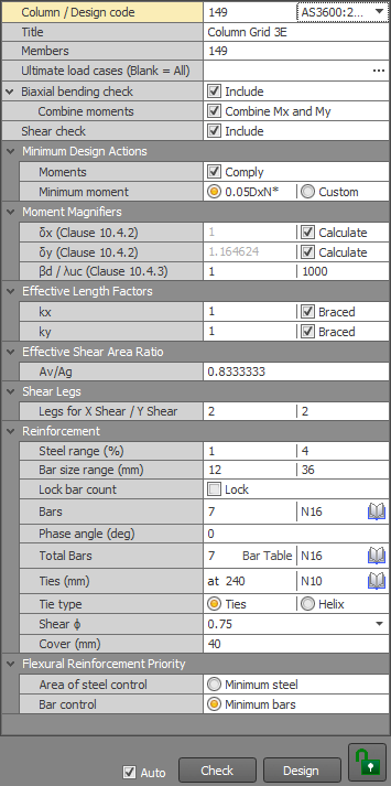
Data panel
The data panel on the left of the concrete column editor lets you make changes to the design data which are then reflected in the diagrams and tables in the editor. More information about specific items in the data panel is presented in the following sections below.
Checking and Designing
When you first create a column and open it in the editor it does an initial design and then displays "Design" at the end of the status bar. If you make changes that initiate a check or if you click the "Check" button then "Check" is displayed at the end of the status bar instead.


Many of the input parameters affect both checks and designs (eg. ultimate load case list, minimum design actions, cover, etc), whereas other parameters are design-specific (eg. design priorities, bar size ranges, etc) or check-specific (eg. bar sizes, bar counts, etc). If you change a parameter that affects both checks and designs then the previous action (ie. check or design) will be repeated, whereas if you change a check-specific or design-specific parameter then it will perform the action appropriate for that change.
Each time you make a change that triggers an automatic re-design or re-check there is a small pause while the action is performed. If you don't want this to happen or if it becomes annoying you should untick the "Auto" option at the bottom and then just click the Design or Check buttons whenever you're ready.

If you have made changes to the reinforcement then the column will become locked to guard against you accidently performing a design and losing your changes. If you really want to do a design then you must click the red locked button first to unlock it.


General data
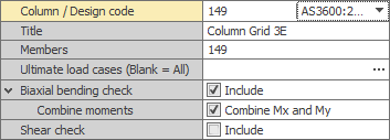
In this panel you can specify the column number, design code, descriptive title, analysis member list, load case list, and the biaxial bending and shear check switches. The column number and analysis member list are normally predefined based on which members you selected when you created the concrete column, however you can change them here if required.
The ultimate load cases are the ones that the strength design is based on and they are usually the combination load cases that have been factored up to ultimate. If you leave this list blank then all analysed load cases will be considered.
Biaxial bending checks are important and so you should always tick the "Biaxial bending check" option unless you specifically want to check uniaxial moments only. For circular columns, the normal procedure for handling biaxial moments is to combine them into a single moment at an angle to the cross section axes and then just treat it as a uniaxial moment problem. You can do this by ticking the "Combine Mx and My moments" option. For circular columns with "Combine Mx and My" unticked or non-circular columns, the biaxial checks are done using the equations in AS3600 clause 10.6.4 or IS456 clause 39.6.
Note that because AS3600 clause 10.6.4 applies to rectangular sections only, you should perform your own independent checks if you have biaxial moments in non-circular columns or non-combined moments in circular columns.
Shear in columns rarely governs, however if you wish to consider shear then you should tick the "Shear check" check box. If shear is being checked then you must also specify a shear area ratio (see below).
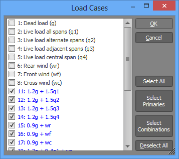
When specifying load case lists, you can either list them directly, or you can click the "..." button to display and select from a list of the load cases currently in the job as shown below.
Minimum design actions
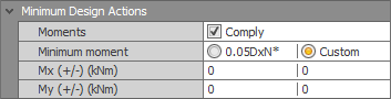
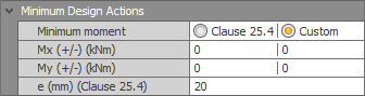
In order to guarantee a robust design, most concrete design codes impose lower limits on the design actions. The minimum design actions can be calculated automatically based on code specific requirements or you can click the "Custom" option and then specify them manually.
AS3600
IS456
Moment magnifiers
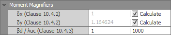
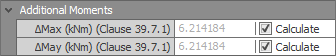
Moment magnifiers (AS3600) or additional moments (IS456) are calculated automatically if the "Calculate" options are ticked, otherwise you can specify them manually.
For AS3600, the moment magnifiers are affected by whether the column is braced or unbraced as defined in the "Column effective lengths" panel below. If braced, the moment magnifier is calculated in accordance with equation 10.4.2. For an unbraced column, the moment magnifier is also based on luc in equation 10.4.3(2). luc should be set by you based on the results of a buckling analysis using reduced section properties of 0.4Ec.If for flexural members and 0.8Ec.Ic for columns. A handy way of applying the reduced section properties is to give the flexural members and the columns separate concrete materials in your SPACE GASS model and then manually reducing the Ec for each material to 0.4Ec and 0.8Ec respectively before performing the buckling analysis.
For the purposes of deciding if a column is "subjected to significant transverse loading between its ends" as per AS3600 clause 10.4.2, SPACE GASS calculates the net transverse load applied between the column ends and then determines what effect that has on the stress at the extreme fibre of the column cross section. If the net transverse load changes the extreme fibre stress by more than 10% of 0.6√f'c then it is considered by SPACE GASS to be a significant transverse load. This is thought to be a reasonable approach by the authors of SPACE GASS in the absence of a precise AS3600 definition of "significant transverse loading". If you think the calculated moment magnifiers are inappropriate for your situation then you should untick the “Calculate” boxes and specify them manually.
AS3600
IS456
Column effective lengths
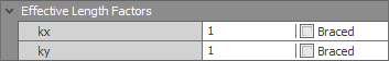
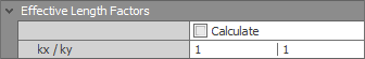
Column effective lengths are not calculated automatically! They are based on the column's overall length multiplied by the kx and ky factors that you specify in this panel.
The "Braced" options (AS3600 only) affect how the moment magnifiers are calculated (see above) and whether or not the column is deemed to be "short" or "slender" based on clause 10.3.1. They do not affect the column effective length calculations.
AS3600
IS456
IS456 calculated k factors
For IS456, the k factors can be calculated automatically based on the stiffness of all the other members that connect to the ends of the column in accordance with IS456 Annex E. The accuracy of the calculated k factors depends on how the column and its restraining members have been modelled.
If an end of the column has a hinged fixity then the restraining members that connect to that end are not considered to restrain the column rotationally in the plane of the hinge. Similarly, if a restraining member has a hinged fixity where it connects to an end of the column then it is not considered to restrain the column rotationally in the plane of the hinge.
The rotational stiffness of restraining members that connect to the ends of the column is based on the length, fixities and moments of inertia of those members. When determining its rotational stiffness, the length of a restraining member is limited to the point where it has a change in direction or twist, a change in section or material, or where another member intersects it at an angle. The stiffness of other members that intersect with a restraining member away from the column are not taken into account. Furthermore, it is assumed that the end of each restraining member away from the column is fixed rotationally, unless the restraining member is a cantilever, in which case it provides no restraint to the column.
The above limitations affect the k factor calculations in varying degrees and it is therefore important that you always check that the calculated k factors are correct before you use them!
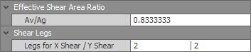
Shear
If shear is being checked then the effective area of the cross section resisting shear must be known. This is calculated by multiplying the shear area ratio (Av/Ag) by the gross cross sectional area (Ag). You should check that the ratio is correct for the cross section shape and the governing shear direction. You can also vary the number of shear legs per cross section in the two column directions.
Reinforcement
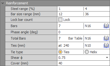
When performing a concrete column design, SPACE GASS calculates the optimal reinforcement (subject to the steel range % and bar size range limits that you specify at the top of the reinforcement panel) and presents it in the lower part of the panel. If you have the "Auto" option at the bottom of the form ticked and the column is not locked (ie. the padlock button at the bottom is green) then whenever you make a change to any of the design parameters, the reinforcement could change.
If you manually change any of the bar counts or sizes in this panel then the column will become locked (ie. the padlock button at the bottom will become red) and any further changes you make to the design parameters will simply cause the reinforcement to be checked rather than be changed. Alternatively, if you wish to lock the bar counts, but still allow the bar sizes to change then you could tick the "Lock bar count" option. In this case a re-design could cause the bar sizes to change but the number of bars would remain as they were.
For AS3600:2018, the capacity reduction factor ϕ for shear can be set in accordance with table 2.2.2.
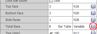
If you wish to change the size of all your bars, you can click the library button (circled below) in the "Total bars" row and then select a new size from the reinforcing bar library. Sometimes this row will also contain the word "Variable" if you have a mixture of different bar sizes in your column.
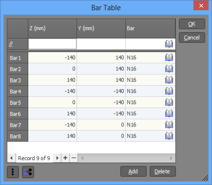
If you wish to change the position or size of individual bars then you can click the "Bar Table" button and then make your changes in the table below. The bar table also lets you add, delete or generate bars, or unify the bar sizes.
Cover
The cover is specified as the clear distance from the edge of the ties to the edge of the concrete.
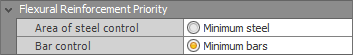
Design priorities
When performing a design, the module evaluates many solutions (sometimes hundreds), discards the impractical ones and then sorts the rest according to the "Design Priority" setting that you have selected. For example, if you have selected "Minimum bars" then it will put the solution that has the minimum number of bars first and present that as the optimal solution. "Minimum steel" gives the most efficient design in terms of total area of steel, however it usually results in quite small bar sizes and so is often impractical. "Minimum bars" gives the best result in most circumstances.
Column view panel
The panel at the top of the column editor shows a 3D or 2D view of the entire column.
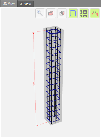
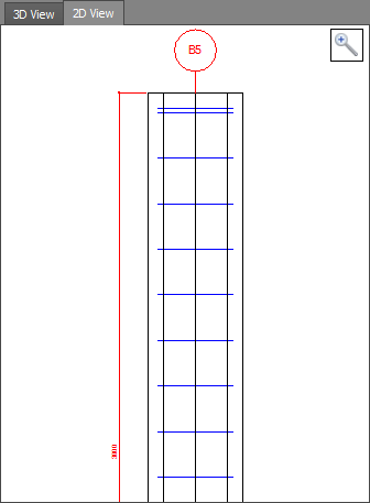
You can also zoom, pan and rotate the column to show the dimensions, cross section and reinforcement in more detail.
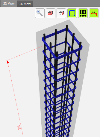
The buttons at the top of the panel let you do a "zoom fit" or quickly switch to a 3D view or side view. You can also turn on/off the stirrups, main bars or dimensions for a clearer view.
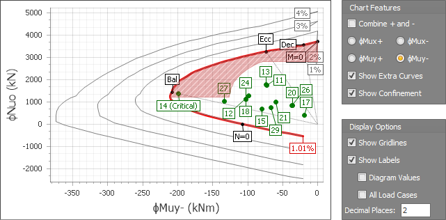
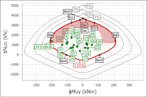
Interaction diagram
The interaction diagram represents the capacity of the column in terms of its axial load versus moment envelope. Interaction curves are included for the actual reinforcement (shown in red) together with the 1%, 2%, 3% and 4% reinforcement percentages. Note that you can vary the 1%, 2%, 3% and 4% values via the concrete column preferences form if you wish to change the steel percentages for the extra curves.
Each load case is shown as a green dot in the diagram and should fall within the red curve. If a load dot falls outside the red curve then failure has occurred. Note that the interaction diagram applies to uniaxial moments only and so you could get a biaxial failure even if all the load dots fall within the curve.
The special points labelled as "Ecc", "Dec" and "Bal" are defined as follows:
Ecc: The minimum eccentricity point that coincides with M=e.N, where e is the minimum eccentricity, M is the moment and N is the axial compression. e = 0.05D for AS3600 (clause 10.1.2) and e = max(L/500 + D/30, 20mm) for IS456 (clause 25.4). If minimum moments are complied with then all the load points should be located on the high moment side of the line connecting the origin with the Ecc point.
Dec: The decompression point that coincides with the extreme tension fibre being zero. This is the point at which it switches from being partially in tension to fully in compression.
Bal: The balanced point at which the tensile steel reaches yield. This is the point at which it switches from a compression failure to a tension failure.
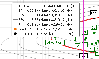
You can hover the mouse cursor over any part of the diagram to show the underlying values at the cursor's location.
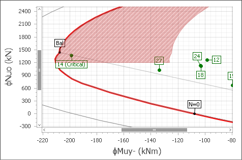
You can also zoom the diagram by placing the mouse cursor at the desired location and then using the mouse scrollwheel. If the zoom feature doesn't work then it is because the diagram doesn't have focus, in which case you should click on it and then try again.
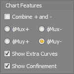
Panels to the right of the interaction diagram let you combine the curves for positive and negative moments or turn on/off various display options.
Confinement region (AS3600 only)
The confinement region is defined by AS3600 as the "Region where the design action effects of combined axial force and bending on a section require confinement to the core". If a load falls within the confinement region and f'c does not exceed 50MPa then SPACE GASS provides confinement to the core in the form of fitments that comply with clause 10.7.4. If a load falls within the confinement region and f'c exceeds 50MPa then SPACE GASS treats this as a failure.
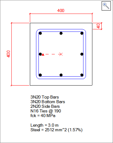
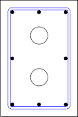
Cross section panel
The cross section panel shows the shape, dimensions and reinforcement for the currently selected zone. You can select a different zone by clicking it in the beam view panel at the top or by selecting it in the data panel on the left.
You can also click the "DXF/DWG" or "Save Image" buttons on the right side of the editor to export the cross section to a DWG or DXF file, or save the cross section image to a metafile (EMF) file. An EMF file can be used to generate a high quality image with no pixilation regardless of how much it is enlarged.


Voids
Multiple voids of any shape or size can be included in the cross section and taken into consideration in the column calculations. You simply add them as negative shapes in the shape builder when you are creating your cross section for the analysis model.
Preferences
You can click the "Preferences" button to open the concrete column preferences form and then change the defaults for various concrete parameters such as the default bar library, spacings, cover, size ranges, colors and other options.

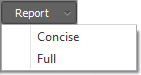
Reports
The reports button lets you generate a concise or a full report for the concrete column. You can also generate reports for multiple slab strips via the "Concrete management tool".
Querying results
You can get a quick summary of the design results for any concrete column by right-clicking on it and then choosing "Concrete Column Design Results" from the popup menu that appears. While the query form is open you can click on any other columns to get their design result summaries too. For more information refer to "Query concrete column design results".