Diaphragms
Diaphragms are an important component of multi-storey building modelling. A diaphragm is typically defined at each floor level to be either fully rigid or semi-rigid in the plane of the floor. Diaphragms are also essential for the correct modelling of seismic accidental eccentricity. This tool allows you to generate the diaphragms along with their associated mass and spectral load cases, taking accidental eccentricity into account.
- Rigid diaphragms are modelled in SPACE GASS by the use of horizontal master-slave constraints that connect the floor nodes to a master node located at the floor's centre of mass. This forces the floor nodes to move and rotate as a unit in a horizontal
plane, while allowing independent movement in a vertical direction.
- Semi-rigid diaphragms give a more realistic representation of a floor's stiffness and are modelled using plate/shell elements in the plane of the floor. The floor still moves and rotates as a unit in a horizontal plane, but there is some flexibility in the plate/shell elements that allows the floor to go slightly out of shape in plan.
Once you have created your multi-storey building model you can use the diaphragm generation tool to create a rigid or semi-rigid diaphragm at each floor level.
Before starting the diaphragm generation, it is a good idea to define the floor levels in the building by using the gridlines tool. This just makes everything clear and means that the diaphragm tool doesn't have to scan the model to try to auto-detect the floor levels.
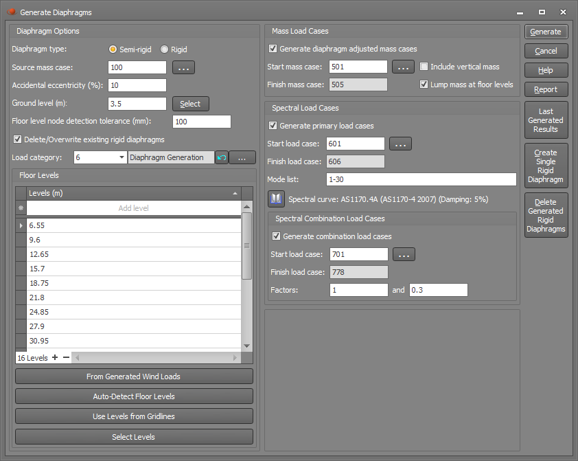
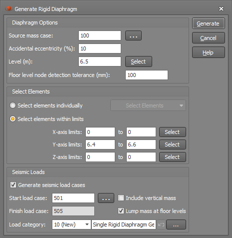
You can run the tool by selecting "Generate Diaphragms" from the "Structure" or "Loads" menus or from the popup menu that appears if you right-click anywhere in the graphics area. You can then create the diaphragms, along with diaphragm adjusted mass cases and spectral load cases via the form shown below.
Diaphragm type
The diaphragm type can be rigid or semi-rigid as explained above. A rigid diaphragm requires master-slave constraints to lock all of the nodes together in the plane of each floor, whereas a semi-rigid diaphragm relies on the stiffness of the floor plates/shells to provide the in-plane rigidity.
Source mass case
The source mass case and its masses should have been created beforehand. It typically contains the self weight of the structure plus any superimposed dead loads that affect the inertial properties of the structure. The source mass case is pivotal to the diaphragm generation because it determines where the centre of mass is located on each floor.
Accidental eccentricity
Accidental eccentricity is required by seismic loading codes to allow for uncertainty in geometric and material properties that could cause extra torsion in the structure during a seismic event. Most loading codes require an accidental eccentricity of around 10% of the overall building dimension normal to the direction of the earthquake.
In a rigid diaphragm, the accidental eccentricity is taken into account by attaching four rigid members to the centre of mass node of each floor, one in each orthogonal plan direction, with a length equal to the accidental eccentricity. The total mass for the floor (based on the total mass from the source mass case) is then lumped at the end of each of those members, creating four new "eccentric" mass cases.
In a semi-rigid diaphragm, the accidental eccentricity is accommodated by manipulating the floor masses rather than changing the structural model at all. This is done by creating four new "eccentric" mass cases that have the same total mass as the source mass case but with the masses factored up on one side of the original CofM and factored down on the other side, effectively moving the CofM by the accidental eccentricity.
Ground level
Specifying the ground level accurately is important because it is used to determine which levels are above ground and which (if any) are below ground. If there are no levels at or below ground level then any mass applied between ground level and half way up to the first floor is discarded.
Floor level node detection tolerance
This tolerance is to allow for any variation in the vertical position of nodes in a floor. Nodes that are located within this tolerance from a specified floor level will be treated as part of the floor. You may need to increase it if you have step-downs or changes in elevation over part of a floor.
Delete/overwrite existing rigid diaphragms
If this option is ticked then any master-slave constraints and rigid members associated with previously generated rigid diaphragms will be deleted or overwritten.
Load category
This field lets you specify which load category any generated masses and spectral loads will go into. For more information refer to "Load categories".
Floor levels
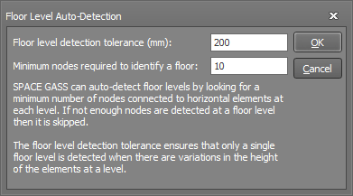
Diaphragms are generated for each floor level specified in this table. If you have already generated some wind loads then the "From Generated Wind Loads" button transfers the levels from that tool into the "Levels" table. Similarly, if you have already defined some gridlines then the "Use Levels from Gridlines" button transfers the gridline levels into the "Levels" table. If you want to select the levels graphically then you can click the "Select Levels" button and then click a node at each level to have it put into the table. Finally, the "Auto-Detect Floor Levels" button looks for a minimum number of horizontal elements in a plane that would identify a floor. You can set a tolerance that allows for some variation in the height of the elements, plus you can control how many nodes within that tolerance are required to identify a floor level.
Mass load cases
Extra mass cases are usually required when diaphragms are generated and so the "Generate diaphragm adjusted mass cases" option should normally be ticked.
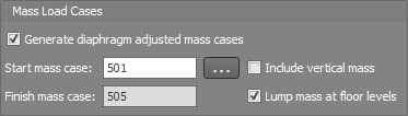
There can be up to five extra mass cases generated as listed below. If the accidental eccentricity is zero then only the concentric mass case is generated. You can control their numbering via the "Start mass case" field". The "Finish mass case" is calculated and displayed automatically.
1. A concentric mass case.
2. A +X eccentric mass case for the earthquake in the Z direction.
3. A -X eccentric mass case for the earthquake in the Z direction.
4. A +Z eccentric mass case for the earthquake in the X direction.
5. A -Z eccentric mass case for the earthquake in the X direction.
Each of the above mass cases combines the lumped and self-weight masses from the source mass case and applies them just as lumped masses. They each have the same total mass as the source mass case.
For rigid diaphragms the extra generated mass cases each contain just one mass that is lumped at the centre of mass or at one of the eccentric positions, whereas for semi-rigid diaphragms they contain lumped masses distributed throughout each floor.
You can also include vertical mass in these extra mass cases by ticking the "Include vertical mass" option, however vertical mass doesn't contribute to the horizontal eccentric effects and so it should usually be excluded here. Vertical mass is normally included in the source mass case anyway, and so its contribution is not ignored.
The "Lump mass at floor levels" option is normally ticked and has the effect of taking the mass that is applied between floors and lumping it at the floors.
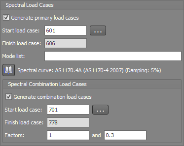
Spectral load cases
Spectral load cases can also be generated at the same time as the diaphragm generation by having the "Generate primary load cases" option ticked. Note that this can also be done at any time later via the "Generate spectral load cases and combinations" tool. For further information about the spectral primary and combination load cases that would be generated you should refer to that tool.
Report
At any stage you can click the "Report" button to get a report of the diaphragm settings.
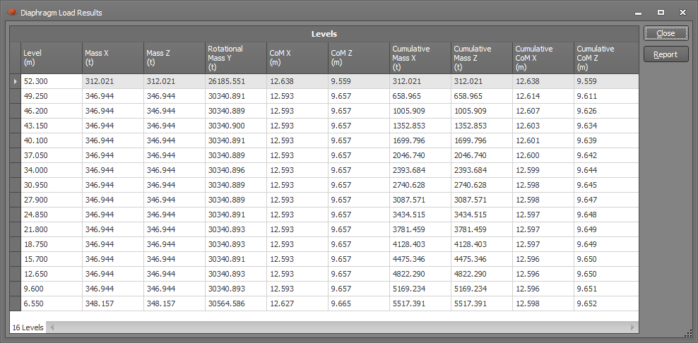
Last generated results
If some diaphragms have already been generated, you can click the "Last Generated Results" button to see a table of the masses that were used in the calculations for each level. The table also includes a "Report" button that gives you a detailed report of the calculations involved.
Create single rigid diaphragm
If you just want to generate a single rigid diaphragm then you can click the "Create Single Rigid Diaphragm" button. It is not applicable for semi-rigid diaphragms.
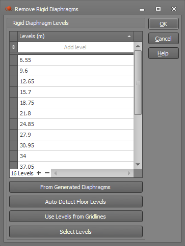
Delete generated rigid diaphragms
You can delete rigid diaphragms by clicking the "Delete Generated Rigid Diaphragms" button and then specifying the levels at which they should be deleted.