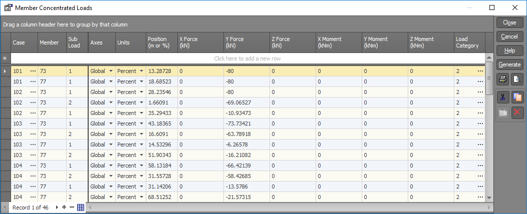
Member concentrated load data

Concentrated forces and moments may be applied to members in either the global or the local axes systems. Such loads can act along or about any of the three axis directions and can be located at any point along the member.
Member concentrated loads may be applied in any number of load cases and may be combined with other load types within the same load case.
Case
Load case to contain concentrated member loads.
Member
Member to be loaded.
Sub load
This allows you to reference multiple concentrated loads on a member in the same load case. Each load is given a sub load number (different to a load case number). For example five concentrated loads applied to a member within the same load case would have sub load numbers of 1,2,3,4 and 5 respectively. Unless there are multiple loads applied to a single member within the same load case, the sub load number should be 1.
Axes
Axes system in which loads are referenced.
|
Choices are: |
Local, |
|
|
Global. |
Units
Units system in which load positions are referenced.
|
Choices are: |
Actual, |
|
|
Percentage. |
Position
The load position is defined as the distance from node A to the load. Depending on the "Units system" selected, this distance may be expressed as an absolute length or as a percentage of the member length. Thus, a member 600mm long with a load at midspan could have the load position specified as 300mm or as 50%.
X, Y and Z forces
Member concentrated forces.
X, Y and Z moments
Member concentrated moments.
Load category
The load category column lets you specify which load categories the loads will go into. For more information refer to "Load categories".
See also Member concentrated loads text.
See also Datasheet Input.
See also Member concentrated loads.
See also View diagrams.