Finite element method
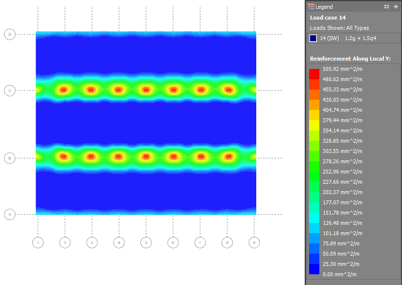
This method calculates the reinforcement in the top and bottom of the slab on an element-by-element basis. You can display the reinforcement for the entire slab by choosing from the various reinforcement contour diagrams via the side toolbar. You can also right-click on any element to reveal the reinforcement calculations for that element. Punching shear is a separate check that is fully explained in the "Punching Shear" section.
Load cases
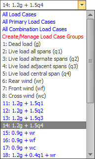
From the load case selection box in the top toolbar you should choose the load case or combination that you want the reinforcement design to be based on. If you change the selected load case while a reinforcement contour diagram is displayed then it will be updated for the new load case. If you have more than one load case selected then the results will apply to the maximums from the selected load cases.
Options
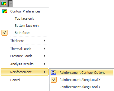
In order to control the reinforcement calculations you can set various parameters via the "Reinforcement Contour and Punching Shear Options" form as shown below. Note that the "Punching shear colors" setting in the form does not apply to reinforcement contours.
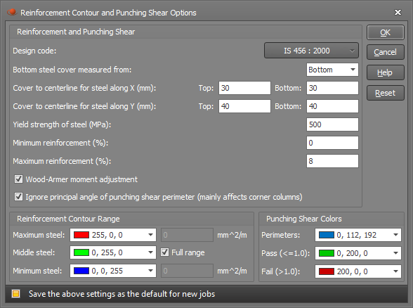
The "Design code" and "Cover" settings are shared with the punching shear and so if you change them for the reinforcement contours then the punching shear calculations will also be affected.
Design code
You can choose between various international design codes including AS3600 and IS456.
Cover
Because the finite element method only calculates areas of steel and doesn't choose actual bars or mesh, the cover you specify must be measured to the center of the reinforcing bars or mesh. If you specify the cover to the edge of the reinforcement by mistake then your design will be unconservative! Note that cover in the strip method is the clear cover measured to the edge of the reinforcement because the actual bars and/or mesh are known.
The bottom cover can be measured from the top or bottom of the slab. You might choose to measure the bottom cover from the top when the slab thickness varies (such as you would get with drop panels) and the bottom layer of bars/mesh maintains a constant distance from the top of the slab.
The "Cover to centerline for bars along X" applies to the bars/wires running parallel to the local x-axis of the plate element and the "Cover to centerline for bars along Y" is for the bars/wires running in the other direction. Because the cover is measured to the centerline of the bars/wires, you must allow for the bar/wire diameter when setting it. The cover must also take into account in which direction each layer is running. In the above form it is assumed that the bars/wires running in the X direction are on top in the top face and on the bottom in the bottom face (ie. closest to the surface of the slab in both faces).
Minimum and maximum reinforcement (%)
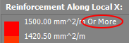
If the calculated area of steel is non-zero and is less than the minimum reinforcement percentage then the minimum reinforcement will be used in those areas of the slab. If the calculated area of steel exceeds the maximum reinforcement percentage then the maximum reinforcement will be used in those areas of the slab, plus the top value in the reinforcement legend will be appended with "or more". Note that if the calculated area of steel is zero then no reinforcement will be specified even if it is less than the minimum reinforcement percentage.
Wood-Armer moment adjustment
If you wish to consider torsion then you should tick the "Wood-Armer moment adjustment" option. The Wood-Armer moment adjustment affects the design moment which usually results in extra flexural reinforcement to resist the torsion.
Reinforcement contour range
If you wish to display the full range of contour values, ensure that the "Full range" option is ticked. If not, you can "zoom in" on a particular range of contour values by unticking the "Full range" option and specifying upper and lower limits. Values that fall within the upper and lower limits will be colored depending on where they fall within the specified color spectrum, and any values that fall outside the limits will be given the same color as values that fall on the upper and lower limits. If you find that the contour diagram is predominantly showing the "middle" color, you may be able to display more color detail by setting a narrower contour range. Note that if you change any of the reinforcement contour range settings or colors, they will also be changed for other general contour diagrams.
Alignment of local axes
It is very important that the local axes of all the elements in the slab are aligned because if the local axes are pointing in all different directions throughout the slab then the reinforcement contour diagrams will also apply to reinforcement in all different directions. When you use the plate mesh tools the local axes are aligned automatically, however if you wish to do it manually or adjust the direction of the local axes for multiple plates then you can do it with the "Align plate axes" tool.
Display side
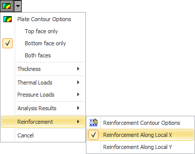
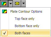
By default the "Display side" is set to "Both faces" which means that when you are looking at the top of the slab you see the contour diagram that applies to the top reinforcement, and when you are looking at the bottom of the slab you see the contour diagram that applies to the bottom reinforcement. If you change the "Display side" to "Top face only" (via the Contour button menu) then the contour diagram for the top reinforcement will be shown regardless of which side of the slab you are looking at. Similarly, "Bottom face only" lets you see the bottom reinforcement diagram regardless of which side of the slab you are looking at. The "Bottom face only" setting in particular is useful because it allows you to get a plan view of the bottom reinforcement without turning the slab upside down. Note that the "top" face is defined as being on the side of the positive local z-axis of a plate element. This means that if the local z-axes for your plate elements are pointing downwards then the "top" face will actually be at the bottom and the "bottom" face will actually be on top.
Reinforcement calculations
You can display the reinforcement calculations for any plate element by right-clicking on it and selecting "Reinforcement results" from the popup menu that appears. While the form is open, you can simply click on any other plates to have their reinforcement calculations displayed.