Draw plate meshed panel
This tool lets you generate complex plate meshed panels by drawing their basic geometry, setting the mesh properties and then generating the mesh.
If you would prefer to create a meshed panel by first drawing members to define it, you should use the "Generate plate mesh from members" tool instead. It has similar capabilities to this mesh tool, albeit with some advantages and some disadvantages.
You should start by drawing nodes that define the vertices of the panel's boundaries, openings, sub-panels and internal walls. Alternatively, you could create the nodes in a datasheet or import them from Excel if you prefer. These nodes are required so that the mesh tool can attach to them when you are drawing the panel to be meshed. Any nodes that already exist as part of your model can also be used as attachment points. Note that circular openings and circular sub-panels can be defined by just a single node at the center. Rectangular openings or sub-panels need a node at each corner. "Sub-panels" are simply panels within a main panel that may have a different thickness, offset or properties to the main panel, such as a drop panel for example.
"Hard nodes" and "hard lines" are simply points or lines that need to be built into the final plate mesh without being moved. For example, a slab could have hard nodes where columns attach and hard lines where walls attach.
After creating all the key nodes, you can start the mesh tool by right-clicking and then selecting "Draw Tools" => "Draw Plate Meshed Panel" from the popup menu that appears.
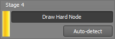
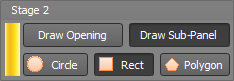
The following form then appears to assist you with the panel generation process. It consists of four stages that you can work through one-by-one. Drawing the panel boundary in stage 1 must be completed first, followed by the openings and sub-panels, hard lines and hard nodes in any order. To proceed with any stage just click its "Draw ..." button and then begin picking nodes to define the geometry of the item being drawn. To move onto the next stage, either click the next "Draw ..." button or click the Next button or press the Tab key on your keyboard.
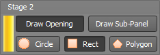
A yellow bar  appears next to the active button so
that you can tell which stage you are working on at any time.
appears next to the active button so
that you can tell which stage you are working on at any time.
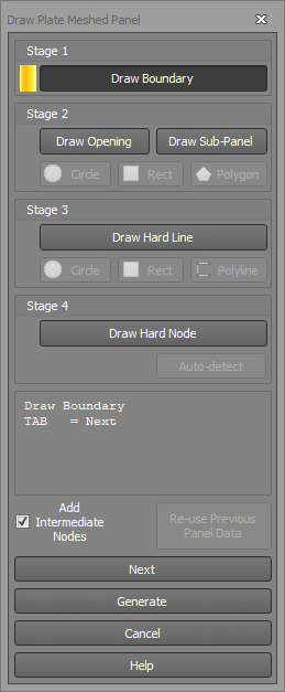
Stage 1 involves drawing the external boundary of the panel. Just click on the boundary nodes in a clockwise or anti-clockwise direction. To complete the boundary just return to the starting point or click the Next button or press the Tab key. If you make a mistake you can press the Esc key to go back point-by-point.

Stage 2 involves drawing any openings or sub-panels you might have inside the main panel. You can also choose between circles or polygons. Circles require you to click a node at the center of the circle, followed by either typing in the radius or clicking another node on the perimeter. Polygons require you to click the nodes around the perimeter of the polygon.
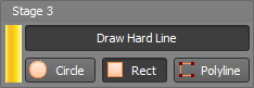
Stage 3 involves drawing hard lines that might define internal walls or other lines that you want to be part of the final plate mesh.
Stage 4 involves drawing any hard nodes that you want to be part of the final plate mesh. These would generally be placed at points where you might want other entities such as beams or columns to connect to the panel. Hard nodes could also be placed where you want to control the size of the elements in certain areas of the panel. For example, you could place a hard node at the center of the panel and then specify a large mesh size for "Hard nodes" in the mesh settings form described below. This would result in a coarse mesh around the center of the panel. Conversely, you could use them to achieve a fine mesh in certain areas.
If you want to go back to repeat or add to a particular stage you can just click the button for that stage, however note this will cause the data for any later stages to be undone.
When the panel is fully defined and you are ready to generate the mesh you should click the "Generate" button.

Before the mesh is actually generated, the following form appears to let you adjust the various settings that control the meshing.
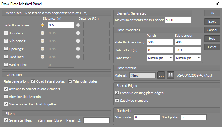
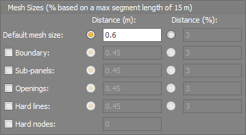
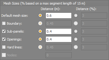
The mesh sizes panel lets you control the size of the elements to be generated in the various parts of the panel being meshed. Each of the mesh size settings can be specified as a length or as a percentage of the maximum segment length. The maximum segment length (15m in this case) is the longest segment in the panel boundary and is determined automatically based on what you have drawn.
The "Default mesh size" is used for any of the settings below it that aren't ticked.
The "Boundary" setting applies to the elements to be generated around the external boundary of the panel being meshed.
The "Sub-panels", "Openings", "Hard lines" and "Hard nodes" settings let you control the size of the elements that will be generated around those entities.
Note that in order to achieve well conditioned elements while preserving compatibility with the surrounding elements, the requested element sizes may not always be achievable.
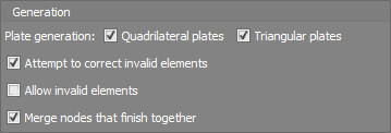
By default, the mesh tool will generate a mixture of quadrilateral and triangular elements, however you can limit it to just one type by unticking either one.
Invalid elements generally occur when an element has an aspect ratio greater than 4:1 or an internal angle greater than 135 degrees. If you tick the "Attempt to correct invalid elements" option then it will re-arrange the mesh and/or split problematic elements into two or three in an attempt to correct them.
Keep in mind that the "Attempt to correct invalid elements" option is not always successful and so occasionally you may get a warning about the mesh not being generated due to invalid elements. In such cases you could either change some of the mesh settings or tick the "Allow invalid elements" option and then once the mesh is generated use the "Find" tool to locate the invalid elements and attempt to correct them manually.
During the meshing process, if two nodes finish up very close to each other and you have ticked the "Merge nodes that finish together" option then the close nodes will be merged into one.
Filters can be automatically generated during the meshing process so that the various components of the finished mesh can be easily isolated and selected. If you leave the "Filter name" field blank then each time you mesh a new panel it will create a filter for that panel called "Panel n", where n is the panel number. If you prefer to define your own filter name then you can enter it into the "Filter name" field.
Filters for openings, sub-panels, hard lines and hard nodes are also created, making it easy for you to select them and change their properties as required.

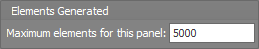
In order to prevent the mesh tool from generating an excessive number of elements, especially if you are unsure of the mesh size settings to use, the "Maximum elements for this panel" setting allows you to set an upper limit that will cause the mesh tool to stop if it is exceeded.
There is still an upper limit of 32765 nodes, members and plates currently in SPACE GASS and so the "Maximum elements for this panel" setting helps you to stay within this limit for your model as a whole. It is planned for this upper limit to be removed in the next major release of SPACE GASS.
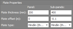
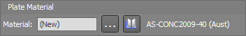
The plate properties and material panels let you set the thickness, offset, type and material of the elements to be generated in the main panel and in any sub-panels. For example, drop panels could be modelled as sub-panels with thicker elements and an offset to keep them level with the top of the slab.
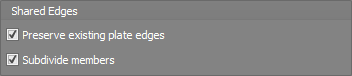
In the shared edges panel you can elect to "Preserve existing plate edges". This applies when a panel being meshed has a common boundary with another panel not being meshed. If you tick this option then the panel being meshed will generate elements along the common edge that match the elements in the other panel so that the two panels are properly connected. If you untick it then the panel being meshed will generate elements independently of the other panel and may result in the two panels not being connected properly. Generally you would untick the "Preserve existing plate edges" option only if the other panel has not yet been meshed.
The "Subdivide members" option controls whether the members you have drawn to define the meshed panel and its sub-panels, openings and internal walls are subdivided or not. If the members are intended to be a permanent part of the structural model then you would probably want them to be subdivided for proper connectivity with the generated plate elements, however if they are just acting as temporary "construction lines" then there would be no need to subdivide them.
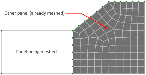
As an example of how to set the "Preserve existing plate edges" option, consider the panel on the left below that is about to be meshed.
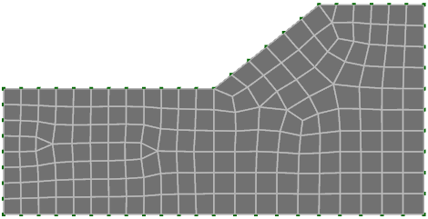
If the "Preserve existing plate edges" option is unticked then the following could occur. You can see that along the common edge there are some locations where a node exists partway along the side of an element. These nodes are not connected to the "Other" panel because elements only connect to other elements via their nodes and not along their edges.

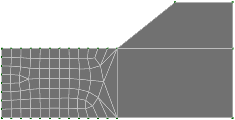
If the "Preserve existing plate edges" option is ticked then you get a much better result with all the elements along the common edge properly connected as shown below.
However if the "Other" panel has not yet been meshed then you should untick the "Preserve..." option in order to avoid the following.
The numbering of nodes and plates being generated can be controlled to some extent via the "Start node" and "Start plate" settings. If you leave them blank then the next available numbers will be used.

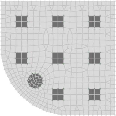
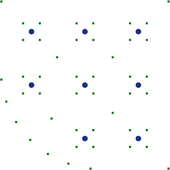
In the following example, a slab supported on columns with drop panels and a circular opening is to be created and meshed. Its key geometry points have been initially defined with nodes as shown below. Note that all of the normal drawing, alignment and attachment tools can be used when drawing the nodes. In this particular example, you could also make use of the copy tool (copy around an arc) to create the nodes around the curved segment of the boundary. In general, any nodes that already exist as part of your model can also be used as attachment points.
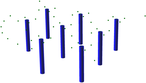
A plan view of the initial nodes and columns is shown below.
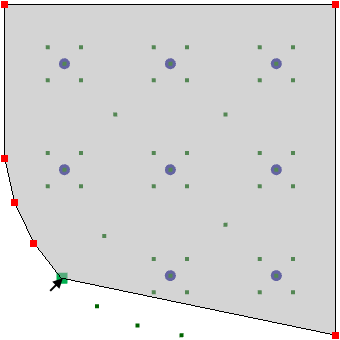
After right-clicking and then selecting "Draw Tools" => "Draw Plate Meshed Panel" from the popup menu that appears, we can define the boundary by clicking the perimeter nodes one-by-one until we return to the start point.
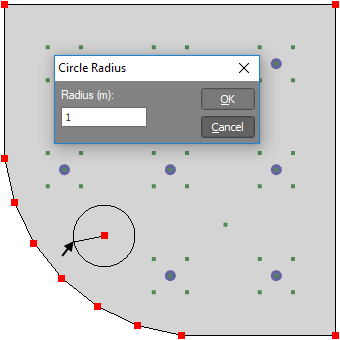
We then move onto stage two, starting with the circular opening. It is just a matter of clicking the "Draw Opening" and "Circle" buttons and then clicking the node at the center of the opening and typing in its radius (1.0 in this case).
The next step involves defining the drop panels around each column. After clicking the "Draw Sub-Panel" and "Polygon" buttons, we click each node around the first drop panel and then move onto the next one, repeating the process until they are all defined.
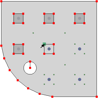
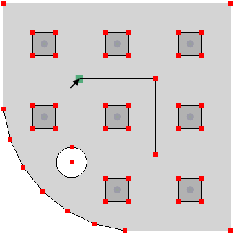
We can then move onto stage 3 by clicking the "Draw Hard Line" and "Polygon" buttons, followed by clicking the three nodes that define the two internal walls.
Note that because the nodes at the top of the columns are contained within sub-panels, they are automatically treated as hard nodes and so there is no need to manually define them using the "Draw Hard Node" button.
Don't forget that at any stage you can go back and undo, edit or add to any previous stages by just clicking any of the "Draw ..." buttons, however keep in mind that this will cause the data for any later stages to be undone.
When everything has been defined correctly we can proceed to the meshing stage by clicking the "Generate" button.
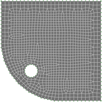
Using a fairly coarse uniform mesh size of 0.6m, the slab is meshed as shown below.
If you look closely you can see that the column nodes, drop panels, circular opening and internal walls are all defined and maintained in their original positions.
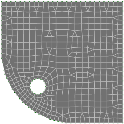
If we wanted to refine the mesh around the circular opening and drop panels, we could click the Undo button (or press Ctrl+Z), re-start the mesh tool via "Draw Tools" => "Draw Plate Meshed Panel" and then click the "Re-use Previous Panel Data" button to recall the previous data. We could then request a smaller mesh size around the opening and drop panels as shown below.

A more refined mesh is then obtained as follows.
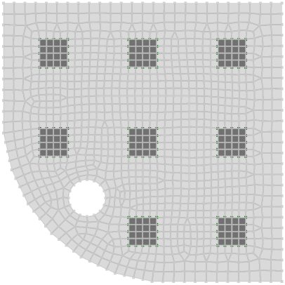
Filters are also created as part of the meshing process, and by selecting the "Sub panels" filter they become more obvious as you can see here. It is then easy to select any of the sub-panels and change their properties without having to worry about accidentally selecting other plate elements not contained within the sub-panels.
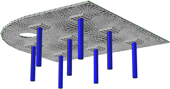
Assuming that no other changes are required, the finished result is a well meshed slab as shown below.
For further information about other plate mesh tools refer to "Mesh tools".