Meshing overview
Correct meshing of plate elements is important in order to achieve accurate analysis results.
The main requirements are as follows:
- Meshing must be performed in order to produce plate elements of a suitable size and shape. In general, small elements produce a more accurate solution than large elements, however it is recommended that the element size should not be much smaller
than its thickness.
- It is recommended that you use a finer mesh (ie. smaller elements) in areas of high stress or in areas that require a greater degree of accuracy. For example, a concrete slab may require a finer mesh over column supports, along edges, at corners and
around openings.
- The local axes of all the plate elements in a panel should be aligned so that any contour diagrams are based on the same direction throughout the panel. If your plate axes aren't aligned then different parts of a contour diagram will be for different directions. You must also ensure that the local z-axes of all the elements in a panel are pointing in the same direction so that the "top" and "bottom" faces are consistent for all elements in the panel. When you use any of the mesh tools they automatically align all the axes for the plate elements that are generated, however the "Align plate axes" tool can be used to do this later if required. You can also use this tool to change all the plate axes in a panel to any desired direction.
The meshing tools currently available in SPACE GASS are summarized below.
Meshing terms
A number of terms used in the following discussion are explained as follows.
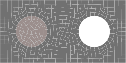
"Openings" are voids in the shape of circles, rectangles, squares or any other general polygon.
"Hard lines" are lines in a meshed panel that must be maintained when the mesh is created. For example, if a slab is supported by an internal wall then the nodes along the top of the wall that connect to the slab would form a hard line that must stay in place as part of the slab's plate mesh.
"Hard nodes" are similar to hard lines except that they are just single nodes. They could typically occur at the ends of internal columns that connect to a slab.
"Sub-panels" are panels within a main panel that could be in the shape of circles, rectangles, squares or any other general polygon. They could be used to model regions with a different thickness, offset or material to the main panel, such as you could get with a drop panel in a slab for example.
Advanced meshing tools
These are the new meshing tools that let you create a well conditioned plate mesh that could contain openings, hard lines, hard nodes and sub-panels.
Generate plate mesh from members
This is an advanced meshing tool that lets you draw members to define a panel, including openings, hard lines, hard nodes and sub-panels, and then convert it into a fully meshed plate panel. Once you have converted the members into the plate mesh you could delete the members if they are no longer required.
This is also an advanced meshing tool that lets you create a fully meshed plate panel by drawing it directly rather than by converting from members. It also lets you define openings, hard lines, hard nodes and sub-panels. Because it doesn't make use of the normal drawing alignment tools in SPACE GASS, you need to create nodes at the key points first and then attach to them while drawing the panel. For this reason, it is sometimes easier to use the "Generate plate mesh from members" tool described above.
This is an advanced version of the original mesh tool. It can be used to determine where selected plates intersect and create a refined mesh. It can therefore be used to connect intersecting plates, repair meshes with many invalid plates, refine the mesh for an entire model or a specific section of the model.
Basic (legacy) meshing tools
This is the original mesh tool in SPACE GASS that generates a basic mesh made from uniform size quad or triangular elements. It may not be the best option to use if you want a mesh that has a mixture of coarse and refined elements.
This is a basic mesh refinement tool that splits the selected elements in half and maintains compatibility with the surrounding elements. It may not be the best option to use if you want a mesh that has a mixture of coarse and refined elements.
Other mesh related tools
If your plate panel is supported on soil you can use this tool to generate spring supports that model the elasticity of the soil based on the tributary area of each node in the panel. The tool can either generate a compression-only member above each spring support, or one-way springs so that uplift can occur.
This tool generates pattern loading on a plate panel for all combinations of alternate and adjacent spans in both the longitudinal and transverse directions.
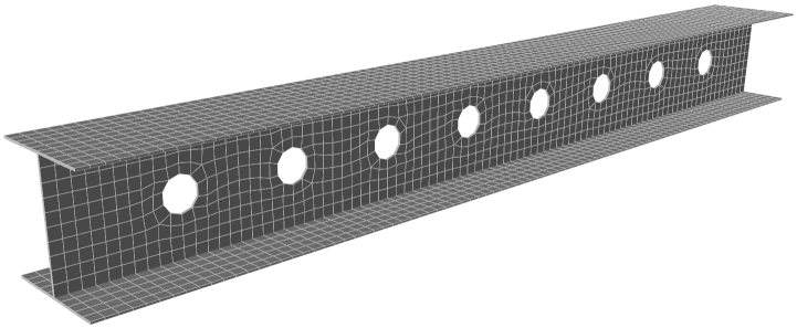
Importing a meshed model from an STL file
SPACE GASS comes with an STL import facility that allows you to generate the complex models in other programs such as Trimble Sketchup or Microsoft 3D Builder and then import them into SPACE GASS fully meshed. The following model is an example of a beam that was generated in Sketchup and then imported into SPACE GASS and meshed. For further information on STL files, refer to "Importing STL files".