Node data
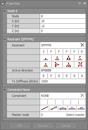
Nodes are used to define the geometry of the structure in 3D space, and to mark the start and end points of members in the model.
There are six possible displacements (degrees of freedom) per node in a 3D frame. They are translation along, and rotation about, X,Y, Z.
Node
The node numbering order is of no consequence and successive node numbers do not have to be sequential. For example, a straight beam with five nodes could just as easily be numbered 24,8,2,13,99 as 1,2,3,4,5. It is possible to leave gaps in the numbering sequence to allow for nodes which might be inserted later.
![]() While the node numbering sequence doesn’t effect the results it is easier to interpret the
results of an analysis if a logical numbering sequence has been used.
While the node numbering sequence doesn’t effect the results it is easier to interpret the
results of an analysis if a logical numbering sequence has been used.
![]() You can renumber nodes at any stage by using the graphics renumbering facility (see also
Renumber).
You can renumber nodes at any stage by using the graphics renumbering facility (see also
Renumber).
X, Y and Z coordinates
Global coordinates of the node that may be positive or negative.
Dummy nodes
These are nodes that are not connected to any members. They are useful as direction nodes or reference points.
See also Node restraints.
See also Master-slave constraints.
See also Members.
See also Nodes text.
See also Datasheet Input.
See also Node properties.
See also Draw.