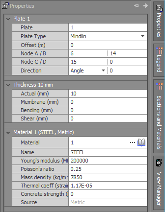
Plate data
A mesh of plate elements can be used to represent walls, slabs, plates, etc. in the real structure. Plate elements can be triangular or quadrilateral with a node at each vertex. They can be connected at their nodes to other non-plate elements such as beams, columns, cables, etc.
Plate
The plate numbering order affects the analysis matrix size, however this is of little consequence if the analysis optimizer is used. The graphical renumbering tool also means that the initial plate numbering order is unimportant because it can be easily changed at any time. Successive plate numbers do not have to be sequential.
Type
Plates can be specified as thick (using Mindlin plate theory – Ref. 19,20,21) or thin (using Kirchoff plate theory – Ref. 22,23). Transverse shear is not considered for Kirchoff plate theory and for the vast majority of applications in structural engineering we would recommend that Mindlin plate theory be used. During the analysis, if "BC" plates are selected then the specified Kirchoff or Mindlin theory is used, however "DL" plates always use Mindlin theory, regardless of whether Kirchoff or Mindlin has been specified.
Direction angle, node, axis
By default, a plate’s local axes are such that x and y are in the plane of the plate and z is normal to the plate. The x-axis is aligned with a line joining nodes A and B and the y-axis is orthogonal with respect to x and z. The direction fields allow you to rotate the x and y axes about the plate’s normal z axis. The purpose for this is to control the axes for which the output results apply.

Plate Axes
It is recommended that for the plate elements in a surface, you align all their in-plane axes in the same direction rather than having them orientated randomly. For circular plates, you may elect to have all of the axes aligned in the same direction or, alternatively, you could align them radially or tangentially depending on which type of output you require.
If the plate axes are orientated randomly then the results will be for different axis directions and they will be difficult to compare. It will also be difficult to produce meaningful contour diagrams if the plate axes are not aligned.
The Align plate axes tool can be used to quickly align the axes for a selection of plate elements. It will also optionally reverse the normal z-axis of some plate elements if they are not all pointing in the same direction. You can also use the Reverse plate direction tool as an alternative way of reversing the normal z-axis.

Direction Angle

Direction Node

Direction Axis
If you are unsure of the orientation of the local axes for a particular plate, you can display them graphically (see also View local axes).
Actual thickness
This is the actual thickness of the plate and is used to calculate it’s self weight and self-mass if they have been specified.
The thickness should be limited to around 15% of the in-plane panel dimensions for Mindlin plates and around 5% for Kirchoff plates. The in-plane dimensions relate to the overall panel size and not the individual element size.
Membrane thickness
This is used to calculate the membrane stiffness of the plate and is usually the same as the actual thickness. The membrane stiffness terms are the ones that affect Fx, Fy and Fxy as shown below. A zero membrane thickness indicates that the actual thickness is used.

Bending thickness
This is used to calculate the bending stiffness of the plate and is usually the same as the actual thickness. The moment of inertia per unit length of the plate is taken as Tb3/12, where Tb is the bending thickness. The bending stiffness terms are the ones that affect Mx, My and Mxy as shown below. A zero bending thickness indicates that the actual thickness is used.

![]() When calculating the design moments for reinforced concrete slabs, the twisting moment Mxy
must be combined with the normal bending moments Mx and My. The Wood-Armer method is commonly used for this and is explained in "Sign conventions". SPACE GASS reports include
the Wood-Armer adjusted moments (as Mxt, Mxb, Myt and Myb), plus the adjustment is available in the reinforced concrete slab design module and when displaying bending moment diagrams in plate strips. For more information refer to "Plate strip data",
"Plate strips" and "Concrete slab design".
When calculating the design moments for reinforced concrete slabs, the twisting moment Mxy
must be combined with the normal bending moments Mx and My. The Wood-Armer method is commonly used for this and is explained in "Sign conventions". SPACE GASS reports include
the Wood-Armer adjusted moments (as Mxt, Mxb, Myt and Myb), plus the adjustment is available in the reinforced concrete slab design module and when displaying bending moment diagrams in plate strips. For more information refer to "Plate strip data",
"Plate strips" and "Concrete slab design".
Shear thickness
This is used to calculate the transverse shear stiffness of the plate and is only used for Mindlin (thick) plate theory. For a uniform plate the shear thickness Ts should be approximately Ta*5/6 to be consistent with Mindlin thick plate theory, where Ta and Ts are the actual and shear thicknesses respectively. The transverse shear stiffness terms are the ones that affect Vxz and Vyz as shown below. A zero shear thickness indicates that the actual thickness is used.
Note that the 5/6 shear thickness adjustment is now done internally during the analysis, however in SPACE GASS 12.91 and earlier versions it was assumed that you would manually set Ts = Ta*5/6 in the plate input data. This means that if you are analysing a model that has Ts = Ta*5/6 in the plate data, you should change it to Ts = Ta, otherwise the 5/6 adjustment will be done twice! This is not quite as critical as it seems because the shear thickness doesn't have a major affect on the results unless very thick panels are being analysed.
Offset
Plates can be offset along their normal z-axis. This may be required to line them up with other interconnecting elements such as other plates or members.

Material
Material property number references a particular material from the material property data. Thus, plates with identical materials would have the same material property numbers.
![]() For an accurate analysis, plates must be properly meshed into elements that are a suitable
size, shape and pattern. For more information, refer to the Mesh tool.
For an accurate analysis, plates must be properly meshed into elements that are a suitable
size, shape and pattern. For more information, refer to the Mesh tool.
![]() For full details of the forces, moments and stresses in plates, refer to "Sign conventions".
For full details of the forces, moments and stresses in plates, refer to "Sign conventions".
See also Material properties.
See also Plates text.
See also Datasheet Input.
See also Plate properties.
See also Draw.