Output
Text reports and graphics can be viewed or printed. Print previews can be obtained and the page setup form gives you full control over the printer selection, paper size, orientation, margins, layout, scales and output format. Text reports can also be configured and saved with a name for later recall or for inclusion in a multiple report.
You can initiate a report by clicking the ![]() toolbar button or selecting the Output menu. You can then choose between
viewing a text report, printing a text report or printing graphics.
toolbar button or selecting the Output menu. You can then choose between
viewing a text report, printing a text report or printing graphics.
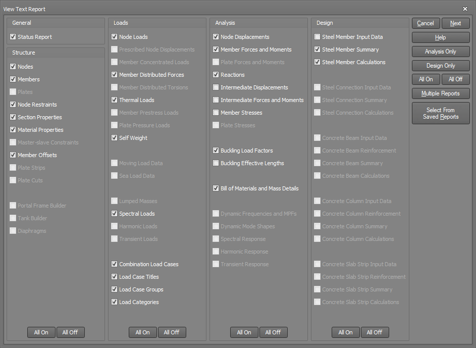
For text reports, the output can be limited to just input data or just output data and even to specific nodes, members, section properties and load cases if required. You can also limit the output to the data specified in any of the graphical filters.

Prior to generating a report, you must choose the items that you want to include in the report by selecting the appropriate check boxes in the above form. You can turn a whole column of check boxes on or off by clicking the "All on" or "All off" buttons at the bottom of the form.
Retrieving a saved report
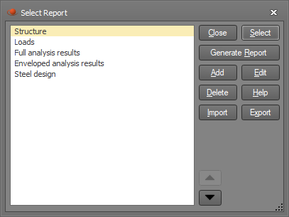
If you have previously saved reports via the "Save" button in the next form, you can select and retrieve one of them by clicking the "Select from Saved Reports" button. This allows you to quickly replicate the selections and settings from a previous or commonly used report without having to manually select all of the desired options again.

It is then just a matter of selecting one of the previously saved reports from the list and clicking the Select button to load it and return back to the main report form. The Add, Edit and Delete buttons also allow you to create and save extra reports or edit or delete saved reports while you are in this form. You can rename a saved report by right-clicking on it and then select Rename from the popup menu that appears.

Running multiple reports
If a number of reports have been saved then you can generate a report containing them all by clicking the "Multiple Reports" button. This is explained further in "Multiple reports".

After completing your selections, you can proceed to the following form.

Saving a report
If you wish to save the current report selections and settings, you can click the Save button and then type in a name that you can use to retrieve it later. You can then retrieve the report later via the "Select from Saved Reports" button without having to manually select all of the desired options again. Saved reports can also be included in a multiple reports. The list of saved reports is stored with the job and so it can be accessed even after the job has been closed and re-opened later.


Filters
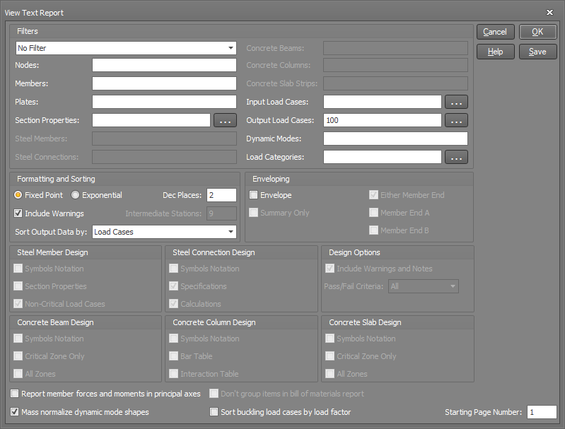
You can select from any of the graphical filters to limit the output report to the data defined in a filter. Alternatively, you can select "Filter in main toolbar" so that the data included in the output report always matches what is shown graphically.
You can also further limit the output data by specifying lists of nodes, members, section properties, load cases, etc. If you want to include all items for a particular list then the list field should be left blank, otherwise type in a list of items (separated by commas or dashes) that you want to include in the report.
Format
Output can be printed in fixed point format (eg. 12.45) or exponential format (eg. 1.245E+01). Fixed point is generally preferred as it is easier to read and allows numbers with different orders of magnitude to be readily identified. It cannot, however be used with very large or very small values. In such cases, exponential format must be used.
As well as specifying the format, you can select the number of decimal places to be included. This cannot be greater than 3 for exponential formatting and cannot be greater than 8 for fixed point formatting. These limits are imposed because of a maximum 10 digit field width. Care must be taken when specifying the number of decimal places with fixed point format. You must ensure that for the range of values likely to be encountered, you don't exceed the 10 digit field width. For example five decimal place fixed point format could only handle values from -999.99999 to 9999.99999. Values outside of this range would simply be printed as "**********".
Section and material properties are always presented in exponential format regardless of the format you specify (due to the extreme range of values usually encountered).
Enveloping
The analysis results data for each load case can be printed separately or can be combined into a load case envelope. If a load case envelope is specified, the program selects and prints the maximum and minimum values from the list of specified output load cases. The report also includes the load case numbers and the matching coincident values that occur at the same location and load case as each maximum and minimum.
At the end of an envelope report is a summary envelope showing the maximums and minimums for a group of nodes and/or members. The summary report also shows the load case numbers and the matching coincident values.
Envelope summary only
By default, envelope reports include an envelope summary at the end, however you can limit your report to just the summary by activating this option in the report generation form.
Member end A or end B
For member end forces and moments, if you wish to limit your envelope to the maximums and minimums that occur at just one particular member end (rather than from either end), you should tick "Member End A" and/or "Member End B". If you tick "Either Member End" (the default setting) then the maximums and minimums will be taken from either end.
![]() The enveloping tool is a fast and convenient way of determining the critical load cases, nodes,
members and plates, regardless of the size of the job.
The enveloping tool is a fast and convenient way of determining the critical load cases, nodes,
members and plates, regardless of the size of the job.
Report member forces and moments in principal axes
Member forces and moments are by default reported in the local axis system of the member, however for members with a non-zero principal angle you can get their principal forces and moments by ticking this option.
Mass normalize dynamic mode shapes
The magnitude of the values in dynamic mode shapes are arbitrary, however in order for them to be used in a response analysis (eg. a spectral, harmonic or transient dynamic analysis) it is convenient to mass normalize them. This means that each mode shape is scaled or normalized to the mass matrix, resulting in a generalized mass of 1.0 for each mode. Mass normalizing the mode shapes just affects the report and has no effect on any of the analysis modules. Note that if you untick this option then the reported mode shapes are unit normalized (ie. the largest translation in each mode is 1.0).
Don't group items in bill of materials report
Identical items in a bill of materials report are normally grouped together, however if you want each item to be reported separately then you should tick this option.
Sort buckling load cases by load factor
The buckling load factor report is usually sorted by load case, however you can have them reported in ascending buckling load factor order by ticking this option. This will cause the load cases that buckle at the lowest loads to be reported first. Note that the sorting for this option is based on the buckling load factor for the first mode only in each load case.
Include warnings
This check box allows you to suppress warning messages relating to the analysis results which sometimes appear in output reports. For example, if a non-linear analysis does not reach the requested convergence in some load cases, then warning messages are posted in the output report for those load cases.
Intermediate stations
SPACE GASS can print the displacements, forces and moments at any intermediate points along a member (not just at the end nodes). Before intermediate member displacements, forces and moments can be printed, you must specify how many equally spaced intermediate member stations are to be considered. The program automatically adds an extra station at each end of the member and at each point of application of a concentrated member load.
Sorting options
Analysis results output can be sorted in one or both of two ways.
-
If sorted in order of load case, the report lists the data for every node (or member) under a main load case heading. This is repeated for each load case.
-
If sorted in order of node/member, the report lists the data for every load case under a main node (or member) heading. This is repeated for each node (or member).
Symbols notation
The steel and concrete design reports allow you to optionally include a summary sheet of the symbols used in the report together with a brief description of each.
Section properties
This allows you to specify whether or not full section properties for the designed or checked members are included in the output. This option is usually suppressed because it enlarges the size of the report.
Non-critical load cases
The majority of the report for a steel member design gives information about the governing failure mode and the critical load case. A summary showing the performance of all of the other load cases can also be included if required. The non-critical load cases summary includes the load factor and the failure mode for each load case.
![]() A description of the failure mode for each load case does not necessarily indicate that failure
has occurred. It simply indicates the failure mode if the loads were increased enough to cause failure.
A description of the failure mode for each load case does not necessarily indicate that failure
has occurred. It simply indicates the failure mode if the loads were increased enough to cause failure.
Connection specifications
This allows you to include or suppress the list of detailed specifications for the bolts, plates, welds, stiffeners and cleats from the detailed output reports.
Connection calculations
This setting allows you to include or suppress the loads, stresses, capacities, factors and other calculated values from the detailed output reports.
Warnings and notes
This check box allows you to suppress warning messages and notes relating to the design results which sometimes appear in output reports.
Pass/fail criteria
For output of steel member and connection design results you can set the "Pass/fail criteria" value to include only the members/connections which have passed, only the ones which have failed, or all members/connections.
After completing the fields in the above form, you can click the Ok (if viewing), Print, Print preview or Page setup buttons.