Step by step guide to concrete slab design
The steps required to prepare the input data for a slab design, run the design and then obtain results are described below.
Model your slab with plate elements
The slab design module requires you to model your slab with plate elements. Of course your model can also contain normal members for modelling columns, beams, braces and the like that connect to the plate elements. The plate elements in the slab should be meshed to a suitable size, taking into consideration that a finer mesh may be required along edges, around voids, at support points (such as columns), at stress concentrations or any other areas of interest. Various mesh tools are available for this purpose.
Drop panels or beams underneath the slab can be incorporated into the slab design by the use of thicker plate elements that have been offset downwards so that their top surfaces line up with the top of the slab. The slab design would then consider them as a combined T or inverted L cross section.
The local axes of all the plate elements in your slab should be aligned so that any contour diagrams (and in particular reinforcement contours) are based on the same direction throughout the slab. If your plate axes aren't aligned then different parts of a contour diagram will be for different directions. You must also ensure that the local z-axes of all the elements in your slab are pointing in the same direction so that the "top" and "bottom" faces are consistent for all elements in the slab. When you use any of the mesh tools they automatically align all the axes for the plate elements that are generated, however the "Align plate axes" tool can be used to do this later if required. You can also use this tool to change the direction of all the plate axes in your slab to match the desired direction of your reinforcement.
In order to choose an initial slab thickness that should result in satisfactory deflections based on L/d ratios, you can use the "Span-to-depth calculator" tool.
Footings
If you are using the concrete slab design module to design a raft footing then correctly modelling the soil stiffness underneath the footing is an important step. The soil stiffness can be modelled using vertical node springs that resist downward loads but allow lift-off. Because the meshing of the footing generally results in elements of various shapes and sizes, calculating the tributary area of each node in order to determine its spring stiffness is not straightforward, and so a "Generate plate spring supports" tool is available for that purpose. The tool also attaches a short compression-only member to each spring support so that lift-off can occur. For further information refer to "Concrete footing design".
Note that a wizard for generating standard raft footings is available via the "Structure wizard". The footing wizard generates the fully meshed model, including compression-only spring restraints underneath and pattern loading.
Apply the slab loads
You can use the normal graphical or datasheet tools to load your slab with self weight, pressure loads, thermal loads and node loads, plus there is a pattern loading tool that allows you to quickly create plate pressure load cases comprised of various adjacent and alternate span pattern loads. It is strongly recommended that you apply the plate loading after the geometry and meshing of the slab is complete.
Decide between the strip method and the finite element design methods
The strip method allows you to define column and middle strips in the critical areas of your slab and then design the reinforcement for each strip, taking into account flexure, shear, torsion and deflection. Mesh, bars and stirrups are selected to satisfy the required areas of steel. A comprehensive report can be produced that includes a schedule of the reinforcement along each strip and the various parameters that the design is based on.
The finite element method designs the slab reinforcement on an element-by-element basis and presents the results as contour diagrams of the top and bottom reinforcement. This method requires minimal input from the user and gives a fast overall reinforcement design, however no mesh or bars are selected and so you must fit them manually based on the calculated areas of steel. Because no bars are selected in the design, the cover you specify in this method is to the centerline of the reinforcement, whereas the cover in the strip method is to the edge of the reinforcement.
Both methods should give similar results, however the different treatment of cover and ductility in the two methods could cause different results in some circumstances. The differences are due to the fact that the strip method selects bars and/or mesh with known properties and dimensions from a reinforcement library, whereas the finite element method just calculates areas of steel. Cover in the strip method is measured as the clear distance from the edge of the outermost bars, mesh or stirrups to the edge of the concrete, whereas cover in the finite element method is measured to the centroid of the reinforcement. Ductility in the strip method is known based on the bars or mesh selected, however the finite element assumes normal ductility reinforcement with a capacity reduction factor of 0.8. If you are using low ductility reinforcement in the finite element method then you could manually increase the calculated areas of steel in proportion to the ratio of the normal and low ductility capacity reduction factors.
Define plate strips (strip method only)
If you have chosen the strip method then you must first define plate strips throughout the critical areas of your slab. It is common to define a strip along each line of columns with a width equal to 25% of the distance to the next line of columns on each side (column strips) plus a strip in-between each column strip with a width equal to 50% of the distance between the lines of columns (middle strips). You would normally define column and middle strips in both the longitudinal and transverse directions so that they cross over each other. Strips may also be required at other locations such as across re-entrant corners. For further information refer to "Plate strips".
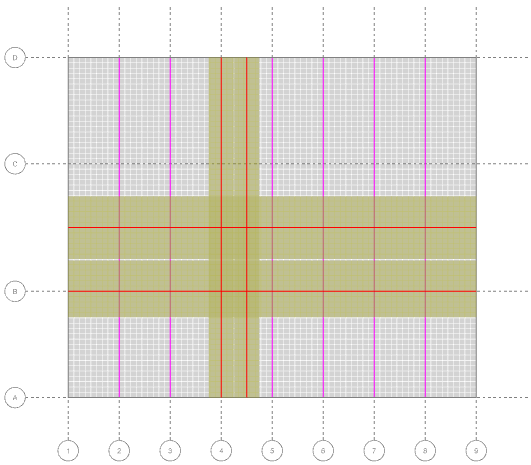
Using the strip method
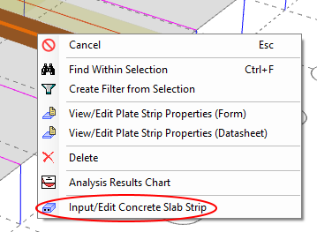
In order to design a slab strip, you should select the plate strip that you want to use, right-click and then select "Input/Edit Concrete Slab Strip" from the popup menu that appears. This will open the slab strip editor and attempt to perform an initial design.
You should carefully set the ultimate, serviceability and sustained load case lists in the editor before accepting any design results. You can also change the other parameters in the slab strip editor to suit your requirements.
You may have to specify different cover for strips that cross each other to allow for the reinforcing crossing over at slightly different levels.
If you want to prevent the sometimes annoying delay that happens due to the design/check it does each time you change a setting then you should untick the "Auto" option near the bottom of the editor and just click the "Check" or "Design" button when you're ready.
If you want to perform a check instead of a design then as soon as you change any of the reinforcement details it will lock the design and perform a check instead.
Once you are happy with the design or check, you should click the Ok button to save the slab strip and exit from the editor. You can then repeat the procedure for the next plate strip.
When your slab strips are defined, you can access all of them via the "Concrete manager". The concrete manager allows you to edit individual strips, run a design or check on all of them or generate reports for all of them.
For further information refer to "Strip method".
Using the finite element method
The finite element method requires you to set the reinforcement parameters, display the reinforcement contour diagrams and select the initial combination load case that the design is to be based on.
You can get to the reinforcement parameters by selecting "Reinforcement Contour Options" from the "Show plate contours" button as shown below. You are then able to select the design code and set the cover, steel strength, minimum reinforcement ratios, Wood-Armer moment adjustment option, etc. For further information refer to "Reinforcement Contour Options".
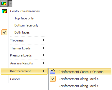
You can then select the "Reinforcement Along Local X" or "Reinforcement Along Local Y" contour diagram to generate a reinforcement diagram for the entire slab.
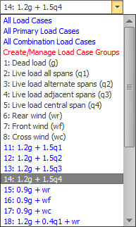
You must also choose the load case or combination that the reinforcement design is to be based on via the load case selection box in the top toolbar. If you change the selected load case then the contour diagram will be updated accordingly. If you have more than one load case selected then the diagram will apply to the maximums from the selected load cases.
For further information refer to "Finite element method".
Check the punching shear
The punching shear check is independent of the strip or finite element methods. You can view the punching shear perimeters via the button on the
side toolbar. The perimeters and utilization ratios can also be labelled
on the slab for your visual checking. The punching shear calculations
are based on the load case or combination that is selected in the
top toolbar. If you have more than one load case selected then
the results will apply to the maximums from the selected load cases.
For further information refer to "Punching
shear".
Get the results
Strip method
If you have used the strip method, you can report the results by clicking the "Report" button in the slab strip editor or you can generate reports for multiple slab strips at once by opening the "Concrete manager", setting the parameters in the "Report" part of the form and then clicking the "Generate Reports" button.
You can also query the results for any strip by right-clicking on it and then selecting "Concrete slab design results" from the popup menu that appears. The query displays a summary of the reinforcement, load cases used, areas of steel and critical deflections. You can then click on any other strip to have the query form updated with the results for that strip.
Finite element method
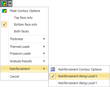
If you have used the finite element method, the results are displayed graphically in the form of reinforcement contour diagrams that you can view or print. A contour diagram is available for reinforcement along the local X and Y plate axis directions for both the top and bottom of the slab. In order to show the bottom reinforcement contour you can either view the slab from underneath or you can select "Bottom face only" from the contour button menu or set it in the "Display side" field of the "Reinforcement contour options" form. This will then show the bottom reinforcement contour from a plan (top) viewpoint. Note that the "top" face is defined as being on the side of the positive local z-axis of a plate element. This means that if the local z-axes for your plate elements are pointing downwards then the "top" face will actually be at the bottom and the "bottom" face will actually be on top.
You can also query the results for any plate element by right-clicking on it and then selecting "Reinforcement results" from the popup menu that appears. The query displays the areas of steel for both directions in the top and bottom of the element plus the key values used in the area of steel calculations. You can then click on any other plate element to have the query form updated with the reinforcement for that element.
Punching shear
The punching shear results are displayed in the form of perimeters and punching shear utilization ratios at each column support location. You can also query the punching shear results by right-clicking on a support column and then selecting "Punching shear results" from the popup menu that appears. The query displays the perimeter length, punching shear stress, utilization ratio and other key values used in the calculation of the punching shear. You can then click on any other support column to have the query form updated with the punching shear for that column.
Re-design/check after a change to the model
If you have made a structural or load change to your model after previous slab designs or checks, you can redo the design or check for every slab strip by opening the "Concrete manager" and clicking the "Design/Check" button. You can control which slab strips are re-designed/checked by listing them in the "Slab strips" field above the "Design/Check" button. Leaving the list blank will re-design/check them all.
If you have used the finite element method then you just need to re-display the desired reinforcement contour diagrams.
Similarly, if you want to re-check the punching shear after a model change then you should just re-display the punching shear perimeters and stresses.